Do you have a question about the Greenlee BLL-200 and is the answer not in the manual?
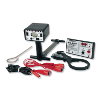
Describes the compact, lightweight kit consisting of a transmitter and receiver.
States the objective of familiarizing personnel with safe operation and maintenance.
Explains the safety alert symbol and its use with signal words.
Defines DANGER, WARNING, and CAUTION levels for hazards.
Warns about electric shock, live circuits, and hazards in utility access areas.
Alerts to hazards in utility access and underground work areas.
Safety measures for unit integrity, test leads, and case operation.
Emphasizes vigilance regarding moving vehicles and machinery in the work zone.
Cautions against repair, extreme temperatures, and humidity.
Notes on voltage limits and electromagnetic interference affecting readings.
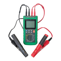
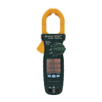
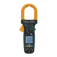
Lists and identifies parts of the transmitter.
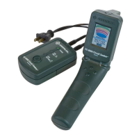
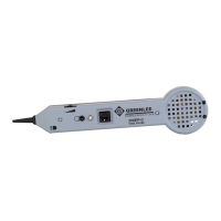
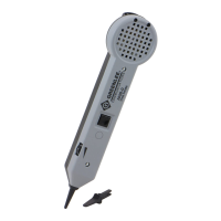
Lists and identifies parts of the receiver.
Explains the numeric and graphical displays for signal strength and depth.
Describes icons for passive mode, signal boost, battery status, and out-of-range.
Defines symbols used on the unit for warnings and insulation status.
Introduces receiver/transmitter, Passive/Trace modes, and signal frequency.
Details Direct Connection, Clamp, and Inductive modes for signal transfer.
Discusses how soil type and moisture content affect performance.
Step-by-step guide for operating the receiver independently in Passive Mode.
Procedures for connecting the transmitter directly to a conductor for tracing.
Procedures for using the clamp accessory to connect the transmitter.
Procedures for using the transmitter in Inductive Mode for signal transfer.
Steps for setting up and using the receiver in Trace Mode.
Details how to scan for signals, interpret indicators, and reset sensitivity.
Step-by-step guide for estimating the depth of a buried line using the BLL-200.
Tips on antenna positioning, checking transmitter connections, and ground points.
Method for tracing non-metallic conduits using fish tape and direct connection.
Technique for identifying bends or tees in buried lines by signal loss.
Method for tracing branches off main circuits using inductive mode and two operators.
Strategies to prevent false readings from nearby conductors and rebar.
Answers on depth in Passive Mode and speaker tone operation.
Explains LCD dashes and troubleshooting incorrect setup.
Clarifies connecting at endpoints versus sources for optimal tracing.
Lists technical parameters for the transmitter: power, voltage, current, frequency, environment.
Lists technical parameters for the receiver: power, depth, accuracy, frequency, environment.
Instructions for safely replacing batteries in the transmitter and receiver.
Guidelines for cleaning the unit's exterior with mild detergent.
Lists part numbers for common replacement items like clamps and test leads.
Outlines the product's warranty coverage and conditions.
Provides contact numbers and fax for technical support and customer service.
| Brand | Greenlee |
|---|---|
| Model | BLL-200 |
| Category | Measuring Instruments |
| Language | English |