4
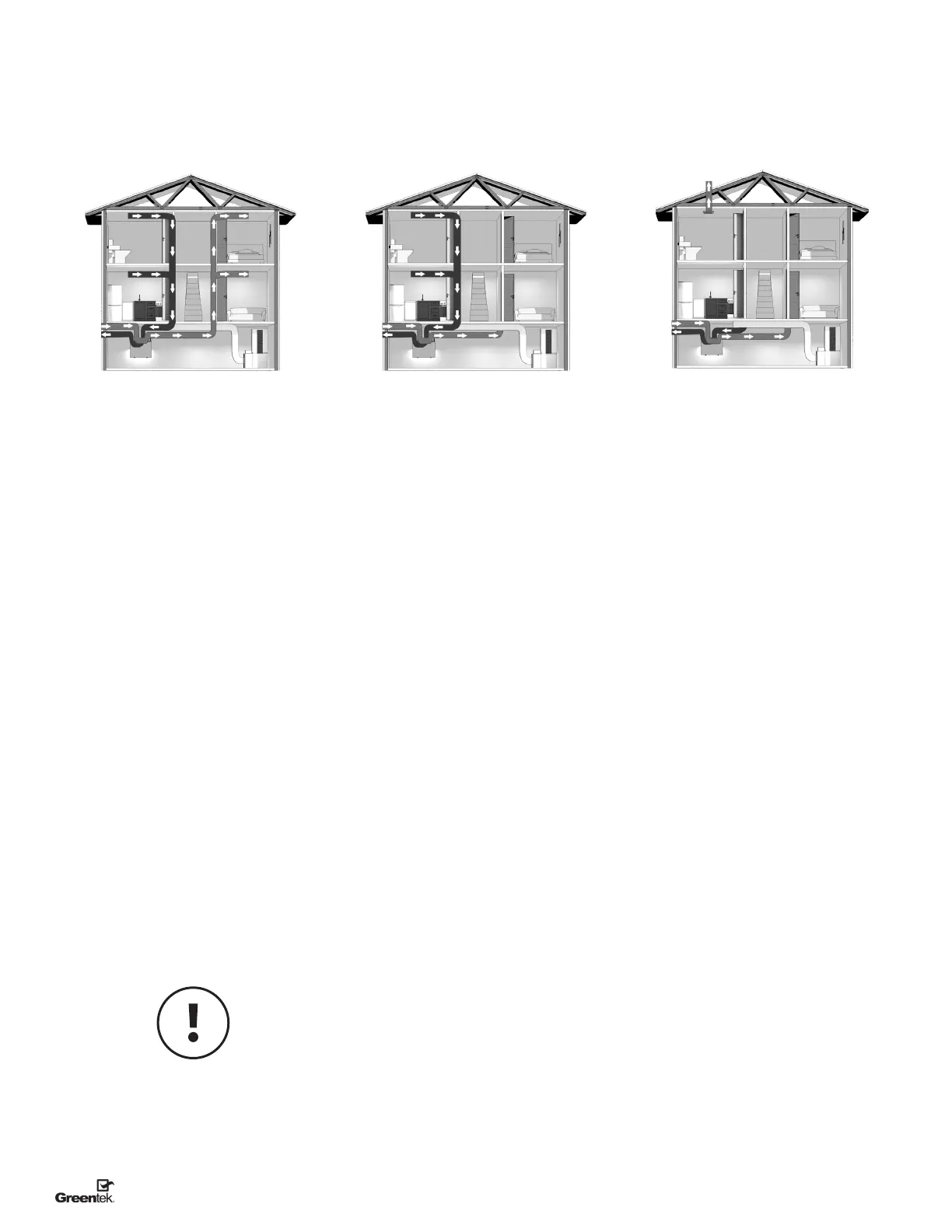
INSTALLATION TYPES
1. Stale air is drawn from areas requiring
local exhaust (bathroom, kitchen, laundry
room).
2. Fresh air is distributed to habitable
rooms (bedrooms, living room)
3. The HRV’s airflow must be balanced after
installation using the procedure found in
the section “AIRFLOW BALANCING.”
Suggested for:
• Hydronic baseboard
• In oor heating
• Electric baseboard
• Mini split heat pump
Benets:
Provides the best fresh air distribution in
the house; lowest operation cost since the
forced air system is not needed.
1. Forced air system blower must operate
when ventilation from HRV is required.
The system should be set to run
continuously or interlocked with HRV. See
forced air system electrical connection.
2. Stale air is drawn from areas requiring
local exhaust (bathroom, kitchen, laundry
room).
3. Fresh air is supplied to the return air
plenum of the forced air system.
4. Before operation, the HRV’s airflow must
be balanced on site. For this, use the
procedure found in the section “AIRFLOW
BALANCING”. During the balancing
procedure, make sure the forced air
system blower is running and the HRV is
running at "Normal" speed.
5. In the case of a multi-zone system,
please contact Greentek customer
service prior to installing any installation
type requiring the use of the forced air
system interlock.
Suggested for:
• Forced air system (central furnace or
central air conditioner)
• When ducting fresh air to living area is
not possible or practical, i.e. expensive
or when the forced air system will
operate year-round
Benets:
Conditions the fresh air prior to distributing
it throughout the house
1. Forced air system blower must operate
when ventilation from HRV is required.
The system should be set to run
continuously or interlocked with HRV. See
forced air system electrical connection.
2. A minimum separation of 1 m (39’’) is
recommended between the two direct
connections.
3. The HRVs exhaust air connection should
be upstream of the HRV’s supply air
connection to prevent exhausting any
fresh air.
4. Before operation, the HRV’s airflow must
be balanced on site. For this, use the
procedure found in the section “AIRFLOW
BALANCING”. During the balancing
procedure, make sure the forced air
system blower is running and the HRV is
running at "Normal" speed.
5. In the case of a multi-zone system,
please contact Greentek customer
service prior to installing any installation
type requiring the use of the forced air
system interlock.
Suggested for:
• When bathroom and kitchen already have
local exhaust system
• May be suitable for retrofitting
Benets:
Least expensive installation type
HRV DUCTING FOR FULLY DEDICATED
SYSTEM
HRV/FORCED AIR SYSTEM DUCTING
FOR PARTIALLY DEDICATED SYSTEM
HRV/FORCED AIR SYSTEM FOR
SIMPLIFIED INSTALLATION
BEST BETTER GOOD
Make sure the HRV is
capable of meeting the
required airow rate.
Example only – duct configuration may differ depending on the model.
 Loading...