300 400 500 700 1000
2000 3000
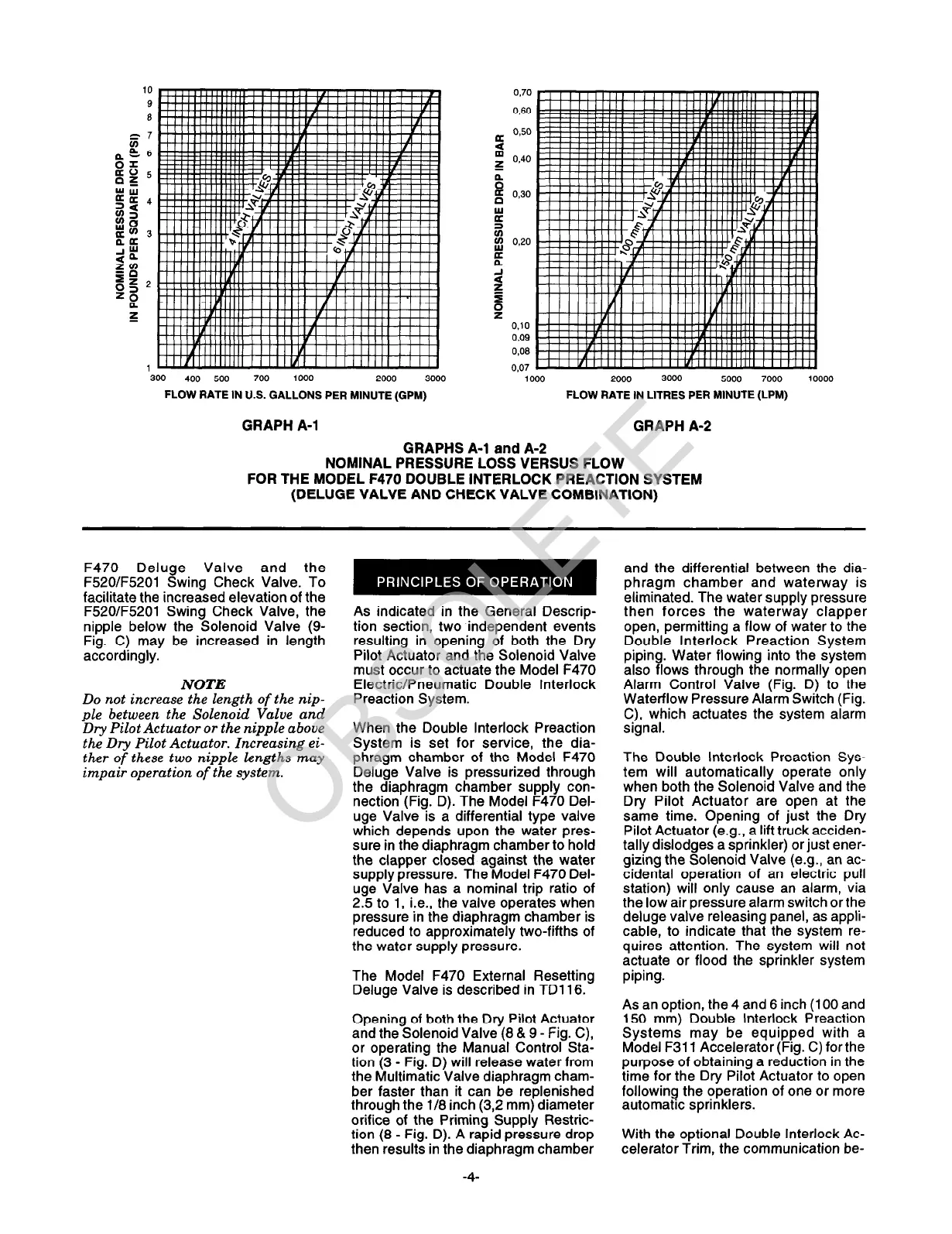
FLOW RATE IN U.S. GALLONS PER MINUTE (GPM)
100 2000 3000 5000
7000 10000
FLOW RATE IN LITRES PER MINUTE (LPM)
GRAPH A-l
GRAPHS A-l and A-2
GRAPH A-2
NOMINAL PRESSURE LOSS VERSUS FLOW
FOR THE MODEL F470 DOUBLE INTERLOCK PREACTION SYSTEM
(DELUGE VALVE AND CHECK VALVE COMBINATION)
F470 Deluge Valve and the
F52OIF5201 Swing Check Valve. To
facilitate the increased elevation of the
F52O/F5201 Swing Check Valve, the
nipple below the Solenoid Valve (9-
Fig. C) may be increased in length
accordingly.
NOTE
Do not increase the length of the nip-
ple between the Solenoid Valve and
Dry Pilot Actuator or the nipple above
the Dry Pilot Actuator. Increasing ei-
ther of these two nipple lengths may
impair operation of the system.
As indicated in the General Descrip-
tion section, two independent events
resulting in opening of both the Dry
Pilot Actuator and the Solenoid Valve
must occur to actuate the Model F470
Electric/Pneumatic Double Interlock
Preaction System.
When the Double Interlock Preaction
System is set for service, the dia-
phragm chamber of the Model F470
Deluge Valve is pressurized through
the diaphragm chamber supply con-
nection (Fig. D). The Model F470 Del-
uge Valve is a differential type valve
which depends upon the water pres-
sure in the diaphragm chamber to hold
the clapper closed against the water
supply pressure. The Model F470 Del-
uge Valve has a nominal trip ratio of
2.5 to 1, i.e., the valve operates when
pressure in the diaphragm chamber is
reduced to approximately two-fifths of
the water supply pressure.
The Model F470 External Resetting
Deluge Valve is described in TD116.
Opening of both the Dry Pilot Actuator
and the Solenoid Valve (8 & 9 - Fig. C),
or operating the Manual Control Sta-
tion (3 - Fig. D) will release water from
the Multimatic Valve diaphragm cham-
ber faster than it can be replenished
through the l/8 inch (3,2 mm) diameter
orifice of the Priming Supply Restric-
tion (8 - Fig. D). A rapid pressure drop
then results in the diaphragm chamber
-4-
and the differential between the dia-
phragm chamber and waterway is
eliminated. The water supply pressure
then forces the waterway clapper
open, permitting a flow of water to the
Double Interlock Preaction System
piping. Water flowing into the system
also flows through the normally open
Alarm Control Valve (Fig. D) to the
Waterflow Pressure Alarm Switch (Fig.
C), which actuates the system alarm
signal.
The Double Interlock Preaction Sys-
tem will automatically operate only
when both the Solenoid Valve and the
Dry Pilot Actuator are open at the
same time. Opening of just the Dry
Pilot Actuator (e.g., a lift truck acciden-
tally dislodges a sprinkler) or just ener-
gizing the Solenoid Valve (e.g., an ac-
cidental operation of an electric pull
station) will only cause an alarm, via
the low air pressure alarm switch orthe
deluge valve releasing panel, as appli-
cable, to indicate that the system re-
quires attention. The system will not
actuate or flood the sprinkler system
piping.
As an option, the 4 and 6 inch (100 and
150 mm) Double Interlock Preaction
Systems may be equipped with a
Model F311 Accelerator (Fig. C) forthe
purpose of obtaining a reduction in the
time for the Dry Pilot Actuator to open
following the operation of one or more
automatic sprinklers.
With the optional Double Interlock Ac-
celerator Trim, the communication be-
 Loading...