INSTALLATION
INSTALLATION
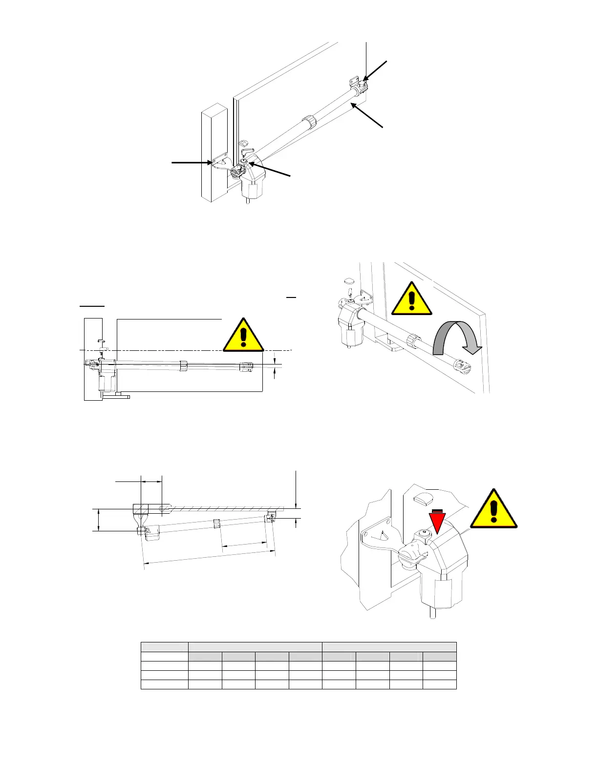
To operate a good installation of the gear motors GR
300/400/600, follow these instructions:
1 - Open the box and take out gear motor. Make sure
that it has not been damaged during the transport.
2 - Make sure that the leaf of the gate is perfectly
horizontal.
3 - Place the gear motor inclined approximately 1º
below the horizontal line (fig 2 )
4
- Fix the support plate A on the pillar beside the leaf,
taking in account the measures shown in Table 1. Do not
forget inclination.
X
Y
6.0
W
Z
5 - Install the gear motor on to the support plate A and
fix it with the bolt.
6 - With gate’s leaf closed, turn and slide the screw of
gear motor’s D shaft, until the end of the stroke
7 - Screw D shaft back on 1 complete turn of 360º.
(fig 4)
8
- Place B support plate in the hole of D shaft and
position it against the gate leaf. Fix it to the gate leaf
taking in account the inclination (point nr.3).
9 - Proceed in the same way with the other gate leaf.
10 - Connect the electrical wires and safety devices:
Place the mechanical limit stops
11 – Place the cover on the unblocking screw (C)
(fig 5)
TAB1
MOTOR ROTATION 95 ° ROTATION 120 °
W X Y Z W X Y Z
GR300 922 140 140 378 922 160 120 378
GR400 1122 145 145 478 1122 170 110 478
GR600 1532 280 280 678 1532 310 120 678
A – Pillar bracket
B – Gate bracket
C – Release
D – Piston rod
FIG 1
FIG 2
FIG 3
FIG 4
FIG 5

 Loading...