1
English
Technical Data
Minimum flow pressure 14.5 psi
Max. operating pressure 72.5 psi
Recommended flow pressure 29.0 - 43.5 psi
Test pressure 87 psi
Flow rate
Per shower max. flow rate 9.5 l/min or 2.5 gpm/ 80 psi
Installation
Note
• In the case of shower doors which open inwards, install
on the appropriate wall side.
• When installing e.g. on plasterboard walls (not solid
walls) it must be assured that an appropriate
reinforcement is in place to ensure sufficient strength.
• Installation height (X) see Fig. [1] and [6] should be
adapted to the body height of the user.
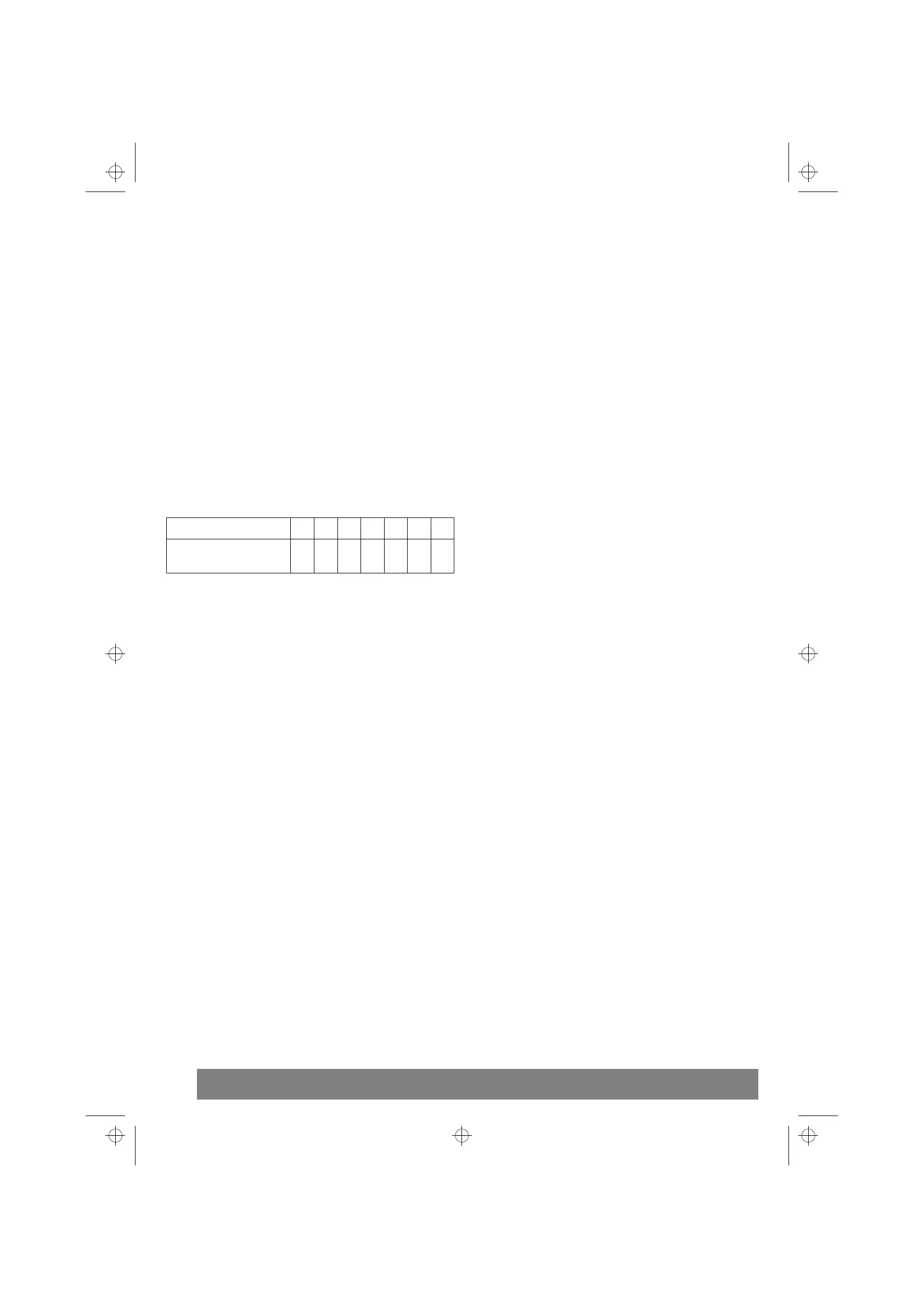
Recommended installation height:
Surface mounting Freehander 27 006
1.Mark position of fixing holes for ø
5
/
16
” (ø 8mm) mounting
plugs with the aid of the supplied rubber sheet (K) and then
drill, see fold-out page III Fig. [1].
When installing directly above the shower fitting, it must be
ensured that the Freehander is higher than the fitting when
folded down, see Fig. [2].
2.Install Freehander, see Fig. [3]. The cap (A) must be
removed prior to installation and re-attached subsequently.
3.Install the attached snap coupling (B) on the supplied
shower spray hose of the shower fitting and attach to the
Freehander connection (C), see Fig. [4].
4.If an additional existing or new hand spray is used, the
supplied outlet nipple (D) must be installed onto the hand
spray, see Fig. [5]. Wall shower holder order no. 28 605 can
be ordered as an additional holder for the hand spray.
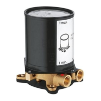
Concealed mounting Freehander 27 007
1.Prepare 1/2” NPT-MIP shower connection, see Fig. [6].
2.Mark position of fixing holes for ø
5
/
16
” (ø 8mm) mounting
plugs with the aid of the supplied drilling template and then
drill, see fold-out page V Fig. [7].
For subsequent installation, as a replacement for an
existing overhead spray with a connection height of
approx. 80
3
/
4
” (2050mm), the user height can be reached
using installation set order no. 27 009 see Fig. [8].
3.Remove cap (E) and union nipple (F), see Fig. [9].
4.Install Freehander, see Fig. [10].
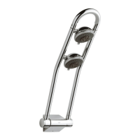
Operation of shower heads, see Fig. [11].
Three functions can be set by turning the adjustment ring (G).
• Front shower (H) Position: MASSAGE
Position: NORMAL
Position: ECO
• Rear shower (I) Position: MASSAGE
Position: NORMAL
Position: STOP= shut off
shower
Important:
• The bracket of the Freehander is not a safety handle and
must not be used as a handle when leaving the bath.
• Exercise caution when touching the Freehander
following thermal disinfection as the water-bearing pipe
reaches a very high temperature.
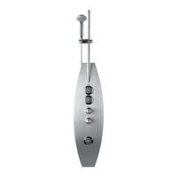
Use of the Freehander
1.Overhead spray, see Fig. [12].
2.Side spray, see Fig. [13].
Maintenance
Inspect and clean all parts, replace if necessary and grease
with special fitting grease (order no. 18 012) if required.
Turn off hot and cold water supply
I. Shower head
Disassembly, see Fig. [14].
The function of the SpeedClean nozzles is guaranteed for a
period of five years.
Simply rub SpeedClean nozzles in order to remove lime scale
from spray jet, see Fig. [15].
Replacement parts, see fold-out page III ( * = special
accessories).
Care
For directions on the care of this fitting, please refer to the
accompanying Care Instructions.
Body height approx. 63” 65” 67” 69” 71” 73” 75”
Installation height (X)
approx.
61” 63” 65” 67” 69” 71” 73”
Please pass these instructions on to the user of the fitting.
The right to make technical modifications is reserved.
i959191.book : i95919us.fm Seite 1 Montag, Januar 14, 2002 12:49 PM
 Loading...