1
English
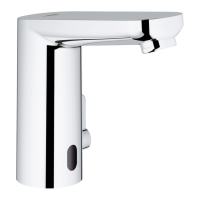
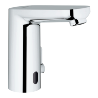
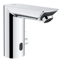
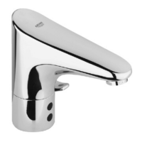
Application
Can be used in conjunction with:
• Pressurised storage heaters
• Thermally controlled instantaneous heaters
• Hydraulically controlled instantaneous heaters
Operation with low-pressure displacement water heaters is
not possible.
Specifications
• Max. flow 1.9 L/min or 0.5 gpm/60 psi
• Flow pressure
- min. 7.25 psi
- recommended 14.5 - 72.5 psi
- greater than 72.5 psi, fit pressure reducing valve
• Max. operating pressure 145 psi
• Test pressure 232 psi
• Temperature
- max. (hot water inlet) 158 °F
• Supply voltage: 6 V-Lithium battery (Type CR-P2)
• Automatic safety stop (factory setting): 60 s
• Tails time (factory setting): 1 s
• Reception range with to Kodak Gray Card, grey page,
8 x 10”, landscape (factory setting): approx. 5“
• Type of protection: IP 59 K
• Battery check (control light)
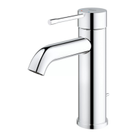
• Water connection cold - RH
hot - LH
Note
Major pressure differences between cold and hot water supply
should be avoided.
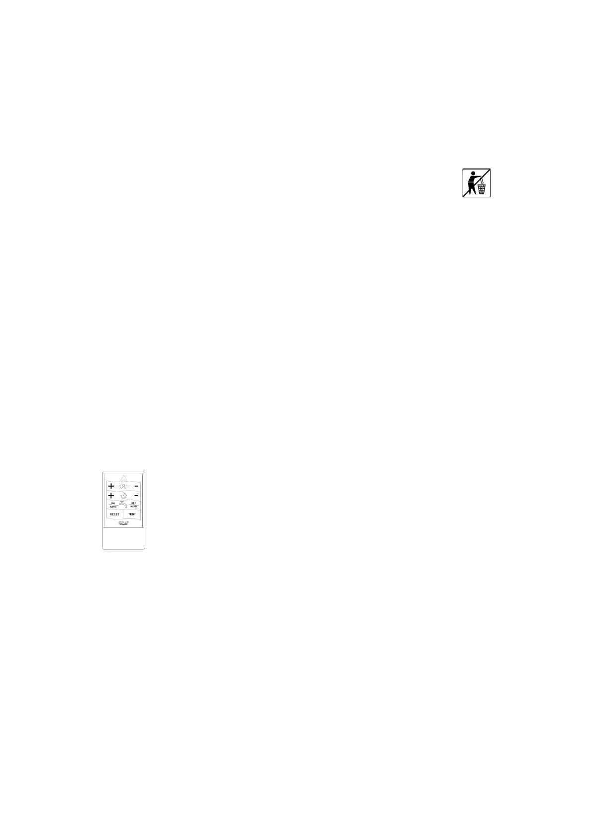
Special accessory, see spare parts fold-out page I.
• With the infrared remote control (ref.-no.: 36 206) the
following settings and changes could be conducted.
• Special wrench (ref.-no.: 19 132) for dismounting flexible
hoses.
• Vandalism hampering concealed mixing spindle (ref.-
no.: 36 209).
• Base to increase faucet and sensor (ref.-no.: 36 210).
• Vandalism hampering anti twist plate (ref.-no.: 42 919).
The anti-twist plate is not combinable with base and not
useful for products with pop up waste set.
Disposal note
Dispose battery properly!
Installation
Flush pipe lines thoroughly!
Mounting
Refer to the dimensional drawings on fold out page I.
Lift rod (A) must be inserted into the faucet body during
installation, see fold-out page II, Fig. [1].
Mount faucet to basin, see Figs. [1] to [3].
Fit pop-up drain (28 957), see fold-out page II, ensure that
flange of pop-up drain is sealed.
Connection
The cold water supply must be connected on the right and the
hot water supply on the left.
Screw adapter (B) by using the filter (C) or seal (B1) to the
thread adapter (D), see Fig. [4].
Connect adapter (D) to the angle stops (or other supply
points).
For the guarantee of a permanently error free operation
the installation of the enclosed adapters with filter
respectively non-return valve is mandatory necessary!
Open cold and hot-water supply and check connections
for leakage.
Operation
The infrared electronics sends invisible, pulsed light.
The infrared electronics is adjusted so that during approxima-
tion of the hands under the spout the watercourse is released.
Leave the hands the spout area the water course with stopped
after 1 s (factory setting).
The range of the sensor depends on the reflection
characteristics of the entering object.
Note:
For anonymous use we recommend the mounting of the
enclosed sticker.
•
us
recep
on range
-
• Adjust tails time (0 - 10 s)
• Set and activate continuous running (thermal
desinfection)
• Switch off solenoid valve
• Restore basic adjustment
• Test mode = waterless simulation
• Adjust safety stop (2 - 420 s)
• Activate and set automatic flushing