Do you have a question about the Grohe GROHSAFE 3.0 35 11 Series and is the answer not in the manual?
| Product Type | Thermostatic Mixing Valve |
|---|---|
| Model Number | 35 11 Series |
| Series | GROHSAFE 3.0 |
| Connection Type | Threaded |
| Max Operating Pressure | 145 psi |
| Temperature Control | Thermostatic |
| Material | Brass |
| Connection Size | 1/2 inch |
| Max Pressure | 145 psi |
| Certification | ASME A112.18.1/CSA B125.1 |
| Safety Features | Scald protection |
| Min Operating Pressure | 0.5 bar |
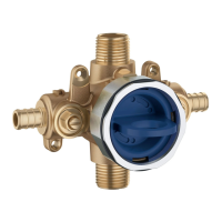
Mount valve body to wall cross brace using wood screws for stability.
Connect hot and cold water supplies per selected valve connection method.
Connect riser pipe to top outlet and tub filler pipe to bottom outlet.
Reinstall plaster guard; finished wall needs 4" opening for trim.
Operate service stops with a flat head screwdriver to shut water off.
Ensure 3-1/2" opening; use self-centering hole guides for accurate placement.
Thread locking screw onto plaster guard to secure valve body in place against the wall.
Connect hot/cold supplies, riser pipe, and tub filler pipe as required.
Operate service stops with a flat head screwdriver to shut water off.
Discard or throw away the plaster guard for this specific installation type.
Thread mounting plate onto valve and install mounting screws securely.
Connect hot/cold supplies, riser pipe, and tub filler pipe as required.
Operate service stops with a flat head screwdriver to shut water off.
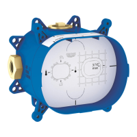
Understand Orientation A (default) and Orientation B (reversed) for flushing.
Follow steps to switch orientations and flush supply lines independently.
Remove flush plug and rethread bonnet nut after flushing is complete.
Part 1 of the assembly: the retaining ring.
Part 2 of the assembly: the service stops.
Part 3 of the assembly: the flush plug.
Part 4 of the assembly: the extension piece.
Part 5 of the assembly: the socket spanner wrench.
Designed for pressurized storage heaters, not low-pressure systems.
Details flow pressure, operating pressure, flow rate, and temperature limits.
Warnings on shut-off valves, soldering, and PEX pipe usage.