13
MODEL 2450A DISASSEMBLY & ASSEMBLY
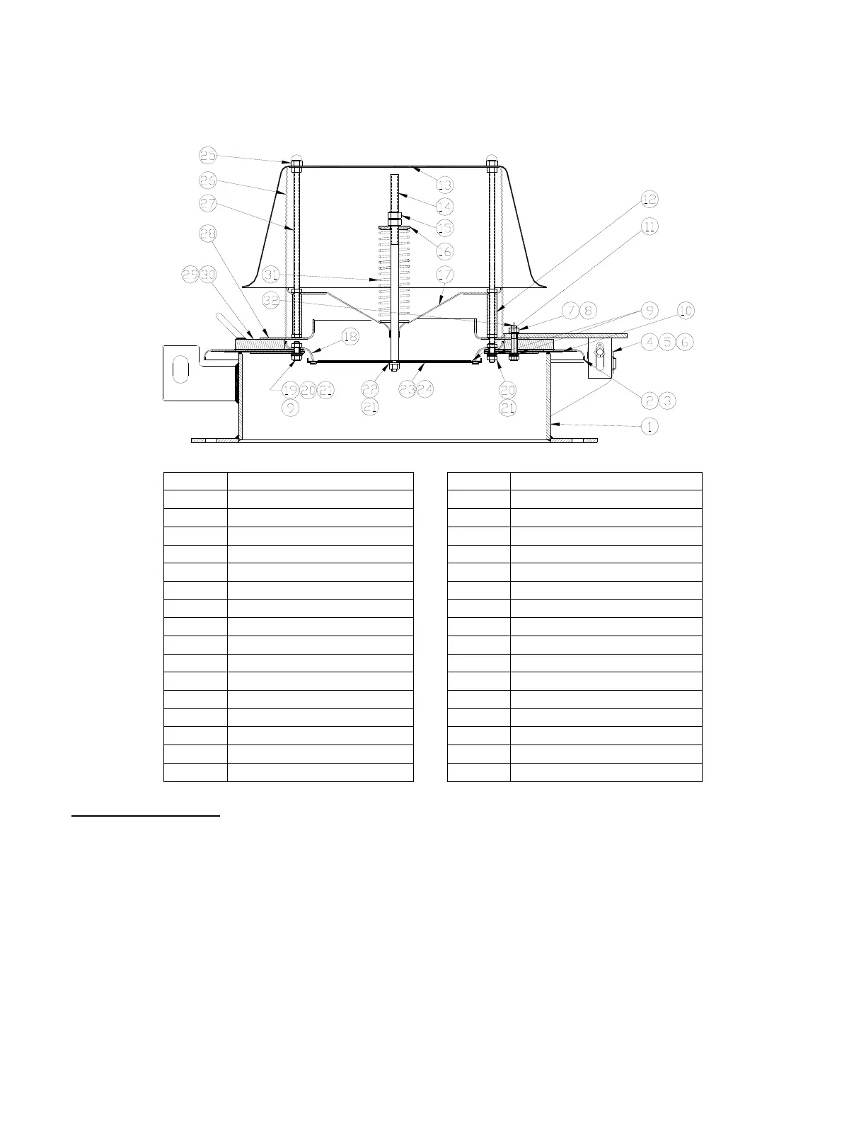
ITEM DESCRIPTION ITEM DESCRIPTION
1 Body 17 Stem Guide
2 Pallet – Pressure 18 Seat – Vacuum
3 Retainer Plate – Pressure 19 Hex Bolt, 3/8-16 UNC
4 Hinge Arm 20 Flat Washer, 3/8", SS
5 Hinge Pin 21 Hex Nut, 3/8-16 UNC
6 Cotter Pin 22 Lock Washer, 3/8"
7 Hex Nut, 3/8-16 UNC 23 Pallet – Vacuum
8 Lock Washer 24 Retainer Plate – Vacuum
9 Washer, 3/8", PTFE 25 Crown Nuts, 3/8- 16
10 Diaphragm – Pressure 26 Screen
11 Diaphragm – Vacuum 27 Weatherhood Post
12 Spacer 28 Water Dam*
13 Weatherhood 29 Weight Plate*
14 Stem – Vacuum 30 Handle*
15 Hex Nut, 1/2-13 UNC 31 Spring
16 Spring Button 32 Hex Bolt, 3/8-16 UNC
* Not used on valves with low settings.
2450 DISASSEMBLY
1. Read “Warning” sections on pages 4 and 6. Remove the valve from the tank.
2. Remove hinge pin [5], and cotter pin [6] from the hinge arm and brackets.
3. Lift pressure/vacuum pallet [2] with attached assembly from body [1].
4. Using the handles [30] on the weight plate [29], or the edges of the pallet [2], lift vertically. Set the
cover on a short length of pipe (minimum 6” high) (Figure 13). This will elevate the retainer plate
peripheral guides above the table so they aren’t bent or damaged.
5. Remove crown nuts [25], lift weatherhood [13], bird screen [26] and set aside.
6. Record “A” dimension (Figure 14). Place a short length of pipe (minimum 6” high) beneath the
vacuum pallet [23] to prevent it from falling. Back the top nut [15] completely off the stem. Compress
the spring using the spring button [16] and grasp the stem (Figure 15). Caution: Remove the
 Loading...