9
nut from the stem. Slowly raise the spring
button to release the spring compression. The
spring force will be in 5 – 30 lb range, depending
on vacuum setting.
6. Using weight plate handles, if included, lift pressure
pallet [2] with attached assembly and remove
vacuum pallet-stem [23, 14] assembly from the
bottom.
7. Remove the nuts on the weatherhood posts holding
the stem guide [17]. Note: For low pressure
settings, a weight plate is added on the stem guide
[17].
8. Lift the spacers [12]. Remove the nuts above the
water dam [28]. Note: Water dam is only used if
weight plate is mounted directly on pressure pallet
[2].
9. Remove the weatherhood posts [27] by loosening
the nuts beneath the pallet.
10. Carefully lift the weight plate [29] vertically.
Caution: This may require a crane due to the
weight. (See Warning on page 5.)
11. Turn pallet assembly upside down (Figure 9).
12. Remove remaining bolts, nuts, and washers [7, 9,
19, 20, 21] to separate the vacuum seat.
13. Lift the retainer plate [3] and diaphragms [10] from
the pressure pallet.
2050A Assembly
Rebuild the valve reversing the disassembly steps.
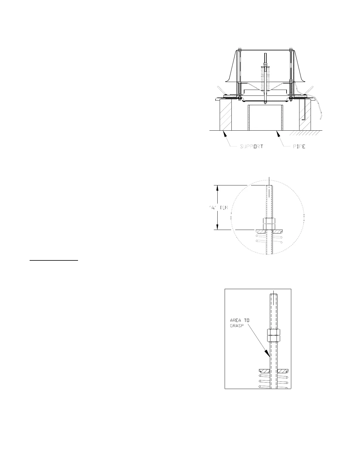
1. Begin by placing the pallet [2] upside down on
support blocks evenly spaced or on a pipe.
2. Wipe clean “air cushion” groove (seat area) in
pallet.
3. Center diaphragms [10] (qty 2) on pallet. See
Figure 3 for orientation of diaphragms, if elastomer
is used.
4. Place retainer plate [3], align with pallet hole
pattern.
Figure 7 : Vacuum Spring Compression
Figure 8 : Loosening Nuts for Spring
Figure 6 : Pallet Support (2050A)
 Loading...