Einleitung / Introduction
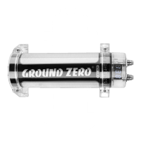
Vielen Dank, dass Sie sich für diesen High Power Ground Zero Kondensator entschieden haben. Bitte
lesen Sie diese Anleitung sorgfältig, bevor Sie mit der Installation des Kondensators beginnen.
Many thanks for choosing this high power GROUND ZERO power capacitor. Please read these
instructions carefully before you install the cap.
WICHTIG / IMPORTANT
Wenn Sie Ihr Fahrzeug zu einer Werkstatt bringen, weisen Sie unbedingt darauf hin, dass ein
Kondensator an der Elektrik angeschlossen ist!
If you bring your car to a garage please tell them that a cap is installed in the system!
Technische Daten / Specifications
1.0 Farad ±50%
Arbeitsspannung / operation voltage
max. 20 Volt DC
Innenwiderstand / internal resistance (ESR)
< 0,0020 Ohm
Arbeitstemperatur / operation temperature
40°C ~ +90°C
ANWEISUNGEN / INSTRUCTIONS
Es ist stets auf die korrekte Polarität zu achten! Zur Ladung und Entladung des Kondensators
muss unbedingt die mitgelieferte Ladeelektronik genutzt werden. Hierzu setzen Sie die kleine Platine mit
den Aussparungen unter die Verschraubung der Anschlüsse des Kondensators und verbinden die rote
Leitung mit dem (+) Anschluss und die schwarze Leitung mit dem (-) Anschluss. Das positive Terminal ist
mit einem (+) Symbol beschriftet, das negative mit einem (-) Symbol. Erst jetzt dürfen die Hauptleitungen
von der Stromquelle (Batterie) an den Kondensator angeschlossen werden. Die grüne LED leuchtet
solange der Kondensator geladen wird auf und erlischt, sobald der volle Ladezustand erreicht ist. Nach
Trennen der Hauptleitungen von der Batterie leuchtet die rote LED auf, welche die Entladung des
Kondensators signalisiert. Sobald diese erlischt, ist der Kondensator entladen.
Always observe the correct polarity! To charge and discharge the capacitor, the enclosed
charging electronic must be used. Place the recesses of the PCB under the terminals of the capacitor and
connect the red wire to the (+) connector and the black wire to the (-) connector. The positive terminal is
labeled with a (+) symbol, the negative with a (-) symbol. Now, the main cables can be connected from
the current source (battery) to the capacitor. The green LED lights up as long as the capacitor is charged
and extinguishes as soon as the full charge state is reached. After disconnecting the main leads from the
battery, the red LED will light up, indicating the discharge of the capacitor. As soon as it will extinguish,
the capacitor is discharged.

 Loading...