Warranty card X1
Installation Procedure
2-2
Note:
The safety part needs to be installed at the top battery, however, once the number of the battery pack is
higher than 7, one more safety part should be installed in the middle battery which is shown the last step.
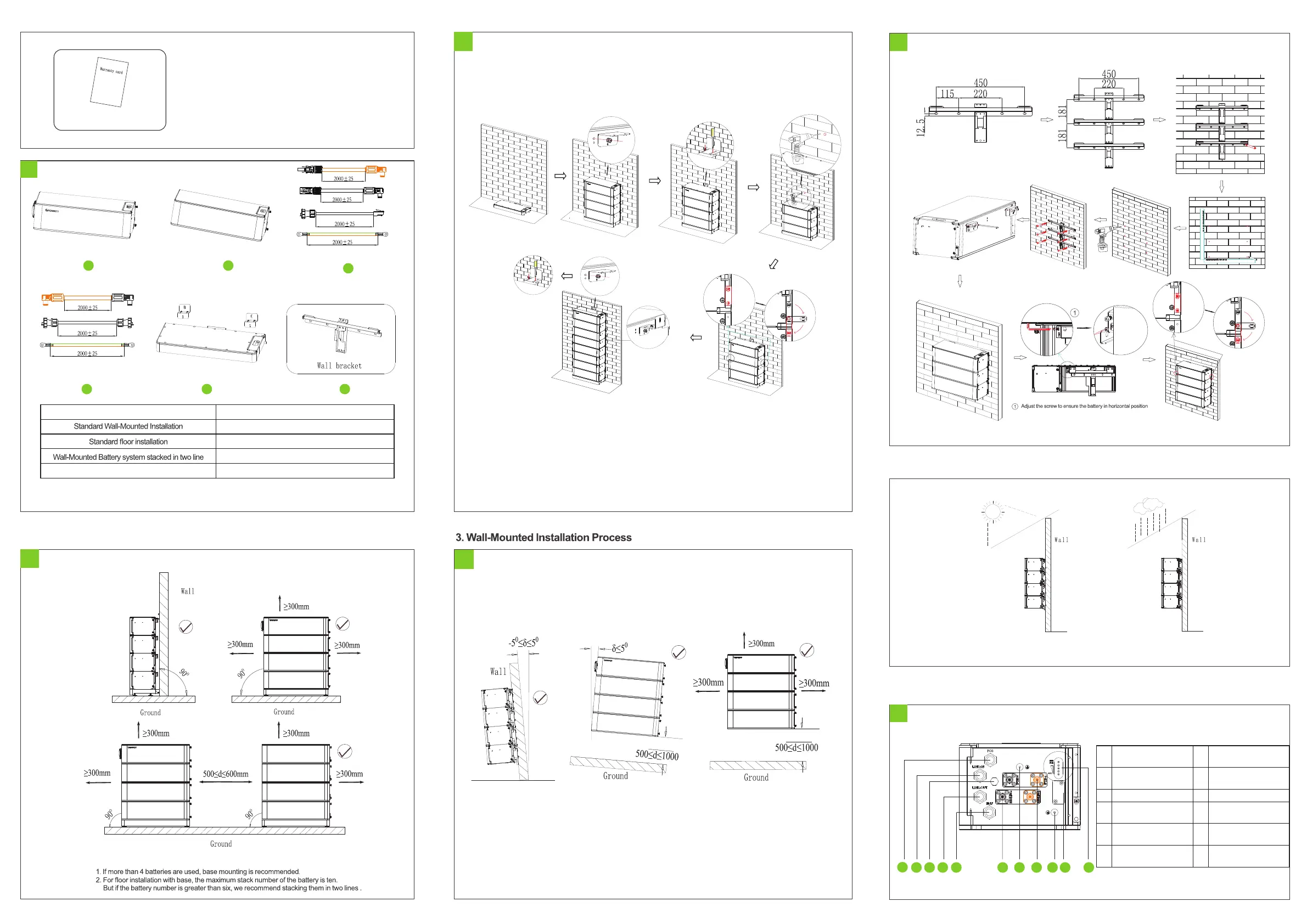
Check accessories
1-3
Installation Method
Compound Mode
A+B+C+F*n
Floor installation battery system stacked in two line
A+B+C+E
A+B+C+D+F*n
A+B+C+D+E*2
Note:
Installation Location Requirements
2.Floor installation with base
Ground(Two installation)rows
Installation Location Requirements
3-1
Note: The number of wall-mount installations should not exceed four.
Please make sure that the weight capacity of wall should exceed 150kg.
Note: Build sun& rain shade to avoid direct exposure to sunlight and rain.
5.Wire Connection
HVC 60050-A1 Interface introduction
5-1
1
2
3
4
5 6 7 8 9 10 11
3
2
4
2-1
3-2 Installation Procedure
4.Install Environment
AR
K
2
.
5
H-A1 S
e
r
i
e
s ca
b
le
AR
K-
2.
5H-
A
1
B
a
s
e
C
D E
A
R
K 2.
5
H
-
A
1
cabl
e
AR
K 2.
5
H
-
A
1
HVC60050-A1
A
B
Note:Wall mounted, one battery with one Wall bracket.
F
Parallel
communication input
Terminal connected to
PCS
Parallel
communication output
Communication with
battery
Terminal connected to
battery
 Loading...