Project2:Layout 1 4/22/11 6:59 PM Page 4
Untitled-1 1 4/22/11 7:07 PM
Project2:Layout 1 4/22/11 6:59 PM Page 4
Untitled-1 1 4/22/11 7:07 PM
Project2:Layout 1 4/22/11 6:59 PM Page 4
Untitled-1 1 4/22/11 7:07 PM
Project2:Layout 1 4/22/11 6:59 PM Page 4
Untitled-1 1 4/22/11 7:07 PM
30
Product Guide
Control panel operation
1
3
5
6
4
2
TM01 9684 2600
Pos. Function Description
1 ON/OFF button
The Pump is started and stopped by
means of the ON/OFF button.
2
Power indicator lights
Indicates that the pump is ready for
operation (green).
3
Indicates that the pump is on
standby (red).
4 Pump ON (green) Indicates that the pump is running.
5 Auto reset (green)
Indicates that the auto reset
function is active. After an alarm,
restarting will be attempted every
30 minutes for a period of 24 hours.
6 Alarm (red)
Indicates that the pump is in alarm
state. Manual resetting is possible
by pressing the ON/OFF button.
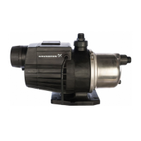
MQ
Flow Based Pressure Boosting System
Part
Number
Model PH & V
AMPS P2
Weight
Net
Pounds
Cord
Connection
Plug
Run Start W HP
96860172 MQ 3-35 1X110-120V 8 29 585 0.75 30.1
7.54’ - 2300mm SJTW-A
18 awg
UL Approved NEMA
5-15P - V125
96860195 MQ 3-45 1X110-120V 10 29 725 1 30.2
7.54’ - 2300mm SJTW-A
18 awg
UL Approved NEMA
5-15P - V125
96860201 MQ 3-35 1X220-240V 4 15 565 0.75 30.1
7.54’ - 2300mm SJTW-A
18 awg
UL Approved NEMA
6-15P - V250
96860207 MQ 3-45 1X220-240V 4.8 15 716 1 30.2
7.54’ - 2300mm SJTW-A
18 awg
UL Approved NEMA
6-15P - V250
Product range and electrical data
Dimensions
TM011 9799
31
Product Guide
MQ
Flow Based Pressure Boosting System
Material specification
Pos. Components Material
2 Support flange PP+30% Glass Fiber HB (f1)
4 Chamber PPO+20% Glass Fiber
7 Drain and priming plug PPO+20% Glass Fiber
10 Self-priming valve PP+30% Glass Fiber
14 Self-priming part PPO+20% Glass Fiber
16 Pump sleeve
Stainless steel,
DIN W.-Nr. 1.4301, AISI 304
42 Tank cover PP+30% Glass Fiber HB (f1)
49 Impeller PPO +20% Glass Fiber-PTFE
51 Motor cover PP+30% Glass Fiber HB (f1)
65 Non-return valve POM+25% Glass Fiber
92 Clamp
Stainless steel,
DIN W.-Nr 1.4301, AISI 304
100a Discharge port PPO+20% Glass Fiber
POM: Polyoximetylen
NR-rubber: Natural Rubber
PPO: Polyphenylene Oxides
PP: Polypropylene
NBR-rubber: Nitrile-Butadiene Rubber
Pos. Components Material
101 Suction port PPO+20% Glass Fiber
103
104
Shaft seal:
Stationary and
rotating part
Carbon/ceramics/NBR rubber
149 Insulation disc PA 5VA (Polyammide)
150
Shaft
Stainless steel,
DIN W.-Nr 1.4005, AISI 416
Motor sleeve
Stainless steel,
DIN W.-Nr 1.4301, AISI 304
164 Terminal box cover PP+30% Glass Fiber 5VA (f1)
174a Pressure switch
POM+25% Glass Fiber / SIL Rubber
(Silicone Rubber)
Pressure switch membrane SIL Rubber - Silicone Rubber.
180 Motor body PP+30% Glass Fiber 5VA (f1)
184 Flow sensor POM+25% Glass Fiber
O-rings NBR-rubber
101
49 16
4
2
100a
14
7
92
150
51
184164 174a 42
103
104
65
10
180
L-DWS-PG-01 8-09.indd 31 11/12/11 12:49 AM
 Loading...