46
Dimensional Drawings
Dimensions and Weights
Pump
Type
Motor Data
D1
Suction
NPT
D2
Disch.
NPT
Dimensions (inches) Ship
Wt.
(lbs)
Ship
Vol.
(Cu
Ft.)
HP S.F. PH Volts A B B1 C E F G H H1 IØ
JPF2A 1/3 1.75 1 115 or 230 1’’ 1’’ 16.2 7.1 9.1 5.5 8.9 0.6 5.5 8.5 6.0 0.38 35 1.5
JPF3A 1/2 1.6 1 115 or 230 1’’ 1’’ 16.2 7.1 9.1 5.5 8.9 0.6 5.5 8.5 6.0 0.38 36 1.5
JPF4A 3/4 1.5 1 115 or 230 1’’ 1’’ 17.3 7.1 9.1 5.5 8.9 0.6 5.5 8.5 6.0 0.38 41 1.5
JPF41A 1 1.4 1 115 or 230 1’’ 1’’ 17.3 7.1 9.1 5.5 8.9 0.6 5.5 8.5 6.0 0.38 43 1.5
Shallow Well Performance Chart
Model HP Depth to Water
Discharge Pressure (PSI)
Shut-
off
(PSI)
Pressure Switch Settings
(PSI)
20 30 35 40 45 50 55
Capacities (U.S. gpm)*
JPF2A 1/3
5 11 7 6 4 3 2 58
20-40
10 10 7 6 4 3 2 56.5
15 9 7 6 4 3 2 54
20 7 6 5 4 3 2 51.5
25 5 4 3 2 1 49
JPF3A 1/2
5 12 11 11 10 7 6 4 73.5
30-50
10 10.5 10 10 9.5 7 6 4 71
15 9 8.5 8 8 7 6 4 68.5
20 7.5 7 7 7 6.5 6 4 66
25 5 5 5 5 4.5 4 4 63.5
JPF4A 3/4
5 15 14 14 13 10 8.5 6 75.5
30-50
10 13 12.5 12.5 12 10 8.5 6 73
15 11 11 10 10 10 8 6 70.5
20 9 9 9 8.5 8 7 6 68
25 6 6 6 6 5 5 5 65.5
JPF41A 1
5 21 20.5 20 20 20 19 17.5 86.5
40-60
10 19 18.5 18 18 17.5 17.5 17 84
15 16 16 16 15.5 15 15 14.5 81.5
20 13.5 13.5 13.5 13 13 12.5 12 79
25 10 10 10 9.5 9 9 8.5 76.5
* Capacities given are for near-sea level installations.
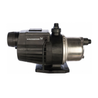
JPF 2A, 3A, 4A, 41A
Product Guide
* Capacities given are for near-sea level installations.
 Loading...