7.4 BMSX system
7.4.1 Flow control and balancing
Flow rates and pressures in a typical BMSX system vary slightly
over the life of the system due to temperature variations, membrane
fouling and feed salinity variations. The rotor of the pressure
exchanger is powered by the flow of fluid through the unit. The
speed of the rotor is self-adjusting over the operating range of the
pressure exchanger pump.
7.4.2 Before startup
Follow these instructions to ensure correct startup of the BMSX
system.
WARNING
Description of hazard
Death or serious personal injury
‐ Make sure that the pump and the system are fully
vented before startup.
1. See the sections on BMS hs pumps and BMS hp pumps.
2. Check that the installation corresponds to the diagram.
A pressure gauge must be installed near each pipe
connection of the PX unit or PX unit array to facilitate
monitoring of PX unit performance.
1
2
4
15
14
13
11
7
8
9
10
17
18
12
20
21
23
22
16
5
6
24
25
26
3
19
A
TM059617
Example of a BMSX booster system
Pos. Description
A Built-in non-return valve
1 Raw-water feed pump
2 Filter
3 Low-pressure switch
4 Flowmeter
5 Pressure gauge (raw water)
6 BMS hs or xl pump with built-in non-return valve
7 Pressure gauge (BMS hs or xl outlet pressure)
8 Vent
9 High-pressure switch
10 Pressure relief valve
11 Pressure gauge (BMS hp inlet pressure)
12 Pressure gauge (BMS hp outlet pressure)
13 BMS hp pump
14 Flowmeter (high-pressure raw water)
15 Pressure gauge (low-pressure raw water)
16 Flowmeter (low-pressure raw water)
17 Membrane filter
18 Permeate
19 Cleaning flush valve
20 Pressure gauge (high-pressure concentrate)
21 Pressure gauge (low-pressure concentrate)
22 Pressure exchanger
23 Concentrate valve
24 Pressure gauge (fresh water)
25 Fresh-water flush pump
26 Flowmeter for permeate
Related information
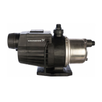
5.2 BMS hs and BMS xl pumps
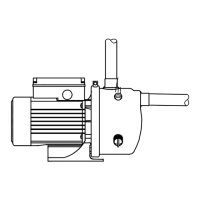
5.3 BMS hp pump
16
English (GB)
 Loading...