English (GB)
5
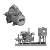
Fig. 2 Example of a diesel-powered Fire HSEF pump set, right view
Fig. 3 Example of a diesel-powered Fire HSEF pump set, left view
TM06 2493 4314
15 23 22 19 24 16 17
71226
27
6
8
9
20
10
18
TM06 2536 4414
Pos. Component Pos. Component
1 Base frame 15 Generator with V-belt and cover
2 Pump 16 Starter
3 Coupling with coupling guard 17 Starter relay
4 Engine, complete 18 Starter batteries
5 Controller 19 Diesel injection pump
6 Fuel tank 20 Fuel filter
7 Tank cap 21 Fuel delivery pump
8 Manual filling pump 22 Speed setting
9 Fuel valve (hidden) 23 Stop lever
10 Drain screw on fuel tank (hidden) 24 Oil dipstick
11 Exhaust pipe 25 Oil filter
12 Heat exchanger 26 Air filter
13 Equalisation tank 27 Automatic air relief valve
14 Cooling circuit
 Loading...