8
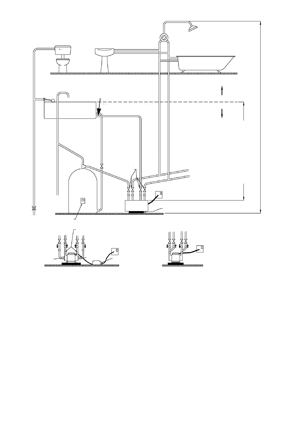
Fig. 4 Negative-head pumps, STN, SSN and STL 2.0 CN
Negative-head pumps
• Either Surrey, York, Warix or Essex flanges can be used,
depending on the cylinder type and installation.
• An Essex flange is recommended for pumps rated 3 bar and
above, i.e. models STN 3.0 B, SSN 3.0 B and STN 4.0 B.
• The hot-water supply to the shower pump must be via a
dedicated supply from the flange.
• Do not fit non-return valves on the inlet pipework to the pump.
The pump must be able to vent back to the cold-water storage
tank and hot-water cylinder.
• Avoid positioning outlets in the cold-water storage tank directly
below the inlet from the water mains supply in order to prevent
air from being drawn into the pump or hot-water cylinder.
• 22 mm pipework should be used to and from the pump.
• Connect the side of the pump with the larger expansion tank to
cold water and the side of the pump with the smaller
expansion tank to hot water.
• The expansion pipe from the hot-water cylinder should always
rise in order to prevent trapped air.
• The outlet pipework from the pump to the shower valve should
rise, where possible, to prevent trapped air.
• Pipework from the pump to the shower valve should go up and
over, rather than under floor.
• Avoid blanked-off pipes (dead legs) which can trap air and
cause problems.
• Avoid kinks in the flexible hoses as this will restrict the flow of
water to and from the pump.
• All pipework should be secured down to minimise noise and
vibration.
• Low-voltage pumps, model STL 2.0 CN, must be connected to
the 230 V electricity supply via the supplied transformer only.
• After commissioning, the pump ensures that all hose
connections are tight to prevent air from being drawn into the
system.
TM04 6989 1310
Cold-water
storage tank of at
least 50 gallons
Supply to another
shower, if required
Hot
Cold
Shower
valve
Domestic
hot-water
supply
Bath
Basin
Cistern
Cold-water supply connection to
pump at least 25 mm below cold-
water supply connection to cylinder
to prevent supply of hot water only
Mount the pump on concrete slab to
reduce noise.
System
vent
230 V,
switched
spur
Low-voltage pumps
must be connected
via transformer only.
See section 8. Technical data for
minimum and maximum inlet
heads from water level to pump
suction port.
Max. 8 m (26 ft)
Negative head
Positive head
Pipework connections, STN and SSN pumps
Flow
direction
Outlet
Inlet
Inlet
Pipework connections, STL 2.0 pumps
Hot-water
cylinder
Recommended location of pump
at base of hot-water cylinder
Hot-water cylinder set
to a maximum of 60 ºC
Water mains supply
Flow
direction
Outlets
Inlet
Inlet
230 V,
switched
spur
Low-voltage
transformer
Cold-water supply to
cylinder, min. 22 mm,
28 mm recommended
Full-bore gate valve
Surrey
flange
Pump
22 mm
service
gate valves
Cold-water supply to
pump, min. 22 mm
Hot-water
supply to
pump, min.
22 mm
Expansion pipe
Outlet
Grundfos.bk Page 8 Thursday, April 22, 2010 10:28 AM
 Loading...