EasyManua.ls Logo

Grundig Fine Arts V 14 DPL-RF User Manual

Grundig Fine Arts V 14 DPL-RF
28 pages
To Next Page IconTo Next Page
Page #1 background imageLoading...
Page #1 background image
Service Manual
HiFi
V 14 DPL-RF
Zusätzlich erforderliche
Unterlagen für den Komplettservice
Additionally required
Service Manuals for the Complete Service
Service
Manual
Service
Manual
Btx * 32700 #
Sachnummer
Part Number 72010-752.15
Änderungen vorbehalten
Subject to alteration
Printed in Germany
VK233 0397
Sicherheit
Safety
Sach-Nr./Part No.
72010-800.00
by
by
DISPLAYS
ON/OFF
HEADPHONES
BALANCE BASS TREBLE
LEFT RIGHT
DEFEATLOUDNESS
DISPLAYS
ON/OFF
HEADPHONES
BALANCE BASS TREBLE
LEFT RIGHT
DEFEATLOUDNESS
POWER
POWER
CD
TAPECD
TAPE
TV/AUX
TV/AUX
TUNER
TUNER
V 14 DPL-RF WIRELESS SURROUND A/V AMPLIFIER
VOLUME
V 14 DPL-RF WIRELESS SURROUND A/V AMPLIFIER
VOLUME
REAR
REAR
CENTRE
CHANNEL
CENTRE
+
+
CHANNEL
PHONO
PHONO
VCR
VCR
DOT
DOT
MODE
MODE
TEST
TEST
SPEAKERS
SPEAKERS
SURROUND
SURROUND
3-STEREO
3-STEREO
A
A
RF
RF
V 14 DPL-RF
Sach-Nr./Part No.
72010-752.15
Question and Answer IconNeed help?

Do you have a question about the Grundig Fine Arts V 14 DPL-RF and is the answer not in the manual?

Grundig Fine Arts V 14 DPL-RF Specifications

General IconGeneral
BrandGrundig
ModelFine Arts V 14 DPL-RF
CategoryAmplifier
LanguageEnglish

Summary

General Information and Specifications

Test Mode Operation

Guide to activating and using the unit's test mode for diagnostics.

Technical Specifications

Detailed technical data and performance parameters of the amplifier.

Disassembly Instructions

Cabinet and RF Board Removal

Steps for removing the main cabinet cover and RF transmitter board.

Front Panel and Audio Board Removal

Instructions for removing the front panel and audio board.

Power Supply and Front Panel Disassembly

Steps for removing power supply and disassembling the front panel.

Service Hints and Safety

RF Transmitter Service Guidelines

Guidelines for servicing the RF transmitter module.

Operating Instructions

Front Panel Controls Overview

Description of the main controls on the front panel.

Power On and Standby Operation

Instructions for switching the unit on and using standby mode.

Speaker Selection and Surround Modes

How to select speakers and use surround sound modes.

Input Source Selection

Guide to selecting audio and video input sources.

Surround Parameter Adjustment

How to adjust surround sound parameters like delay and levels.

System Remote Control Operation

Information on operating the remote control and other devices.

Adjustment Procedures

Quiescent Current Adjustment

Procedure for setting the quiescent current for the amplifier.

Circuit Diagrams and PCB Layouts

Wiring Diagram

Schematic showing internal wiring connections between boards.

Audio Path Diagram

Diagram illustrating the audio signal flow through the unit.

Power Supply and Related Boards Layout

Layouts for Trafo, Fuse, RC Bus, and AC Outlet boards.

Audio and Headphone Boards Layout

Layouts for the Audio and Headphone circuit boards.

Display Board Layout

Layout of the front panel display circuit board.

Volume and Control Boards Layout

Layouts for the Volume and Control circuit boards.

DPL and Logic Board Layouts

Layouts for the DPL processing and logic circuit boards.

Audio Center Board Layout

Layout for the audio center circuit board.

DPL and Volume Board Layouts (Continued)

Additional layouts for DPL and Volume circuit boards.

Control and Audio Center Board Layouts (Continued)

Additional layouts for Control and Audio Center circuit boards.

Various Board Layouts (Continued)

Layouts for Trafo, Fuse, RC Bus, and AC Outlet boards.

Audio and Headphone Board Layouts (Continued)

Additional layouts for Audio and Headphone circuit boards.

Spare Parts List and Exploded View

Exploded View

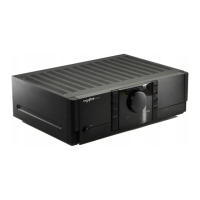
Visual representation of the unit's components for identification.

Spare Parts List

Comprehensive list of all replaceable parts with part numbers.

Related product manuals