Do you have a question about the Grundig GSS STC 160 and is the answer not in the manual?
Essential safety precautions for operation, installation, and environment, including fire and electrical hazards.
Lists included items like the head-end station, power cord, cables, and manual.
Refers to website for modules and accessories.
Explains symbols like important notes, electrical shock, general notes, and button functions.
Details EU directives, ambient temperature, dimensions, weight, power supply, and mains voltage.
Describes modular design, expansion options, power supply, and software update procedures.
Illustrates and labels the front cover components like locking and fastening screws.
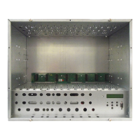
Details front view components like knock-outs for RF output, SAT IF distributors, control panel, and F terminals.
Illustrates and labels rear panel connectors like power socket, switch, earth terminal, SAT IF inputs, and RF output.
Identifies control panel elements: LC display, contrast button, mode indicator, function buttons, and SUB-D socket.
Instructions for loosening screws and removing the front cover.
Steps to remove locking and fastening screws to detach the base plate.
Guides on relocating and mounting the PE connection terminal with caution for proper connection.
Instructions for inserting F terminals into knock-outs on front/rear panels with tightening caution.
Details on mounting a fan to the base plate and making its electrical connection.
Detailed steps for securely mounting the head-end station to a wall.
Instructions for mounting the head-end station in an upright position.
Guide for installing the head-end station into a standard 19-inch rack cabinet.
Step-by-step guide on opening locking devices, inserting modules into slots, and closing locks.
Details on making potential equalization using a PE wire and connection terminal as per DIN EN 60728-11.
Instructions for connecting the power cord, including routing through a ferrite sleeve for EMC compliance.
Describes connecting the DC cable of an input distributor to power supply contacts.
Guidance on connecting RF lines using F terminals, specifically SAT IF cables from LNBs.
How to adjust the contrast of the LC display using the designated button.
Covers setting output levels, signal standards, and configuring a control panel PIN for security.
Instructions for securely tightening cable connections, F terminals, and cover screws to ensure EMC compliance.
| Category | Network Hardware |
|---|---|
| Model | GSS STC 160 |
| Frequency Range | 950 MHz - 2150 MHz |
| Connector Type | F-connector |
| Operating Temperature | +50°C |