EasyManua.ls Logo

Grundig GV 8400 HiFi User Manual

Grundig GV 8400 HiFi
40 pages
To Next Page IconTo Next Page
Page #1 background imageLoading...
Page #1 background image
Service Manual
Video
Zusätzlich erforderliche
Unterlagen für den Komplettservice
Additionally required
Service Documents for the Complete Service
Ergänzung
Supplement
Service
Manual
Service
Manual
Service
Training
Entwicklungscode AA
Evolution Code AA
GV 8000 GB
GV 8000 SV
GV 8000 SV/5
GV 8050 SV
GV 8300 SV
GV 8300 SV/5
GV 8400 GB
GV 8400 HiFi
GV 8400 HiFi/5
GV 8400 NIC
GV 8450 HiFi
KV 8001 VPS/5
KV 8301 VPS/5
KV 8401 HiFi/5
Palermo/SE 8100 SV
Sevilla/SE 8105 HiFi
GV 27…
GV 47…
GV 7…
Sach-Nr./Part No.
72010-530.25
Btx * 32700 #
Sachnummer
Part Number 72010 530 2600
Änderungen vorbehalten
Subject to alteration
Printed in Germany
VK21/VK211 0898
STOPEJECTINSTALL
STAND BY
RECORD
8
p
o
uu
uu
.
AUDIO IN VIDEO IN
LR
PAL / SECAM
Sicherheit
Safety
Sach-Nr./Part No.
72010-800.00
GV 27…
GV 47…
GV 7…
Sach-Nr./Part No.
j 72010-531.40
k 72010-531.41
GV 8000…
GV 8300…
GV 8400…
Sach-Nr./Part No.
72010 530 2600
Grundig Service
Hotline Deutschland...
TV
TV
SAT
VCR/LiveCam
HiFi/Audio
Car Audio
Telekommunikation
Fax:
Planatron
(8.00-22.00
Uhr)
0180/52318-41
0180/52318-49
0180/52318-48
0180/52318-42
0180/52318-43
0180/52318-44
0180/52318-45
0180/52318-51
0180/52318-99
...Mo.-Fr. 8.00-16.30 Uhr
0180/52318-40
0180/52318-50
Telefon:
Fax:
Technik:
Ersatzteil-Verkauf: ...Mo.-Fr. 8.00-19.00 Uhr
Question and Answer IconNeed help?

Do you have a question about the Grundig GV 8400 HiFi and is the answer not in the manual?

Grundig GV 8400 HiFi Specifications

General IconGeneral
TypeDVD Player
Remote ControlYes
Supported Disc TypesDVD+R, DVD+RW, DVD-R, DVD-RW, CD-R, CD-RW
Video OutputComposite, SCART
Audio OutputStereo
ConnectivitySCART

Summary

General Section

Introduction

Overview of the supplement manual, technical differences, and new information.

Video Recorder Overview

Comparative table of features and modules for various Grundig video recorder models.

Test Equipment

Contact details and information for Grundig's test and measuring equipment.

Operating Elements

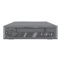
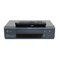
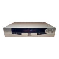
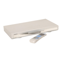
Detailed description of the video recorder's controls and remote control functions.

Child Lock

Instructions on how to enable and disable the child lock feature on the recorder.

Service Hint

Notes and important considerations for performing service on the video recorders.

PCBs and Circuit Diagrams

Wiring Diagram

Illustrates the electrical connections and wiring layout of the video recorder's components.

Block Circuit Diagram (Power Supply / Bus System)

Functional block diagram detailing the power supply and bus system architecture.

Circuit Diagram Sections

Layouts and diagrams for specific circuit blocks like VS/AL, VS-SEC, VPS/PDC, AF, HV, DE-DC.

Block Circuit Diagram (Video/Chroma)

Block diagram illustrating the video and chroma processing circuitry.

Signal Processing (VS) Circuit Sections

Diagrams for VS signal processing blocks including Head Amplifier (HA).

Block Circuit Diagram (Standard Sound)

Block diagrams for standard sound circuits: Frontend, I/O, Display, Deck, and Audio.

Block Circuit Diagram (FM Sound)

Block diagrams for FM sound circuits: Frontend, FM-Audio, NICAM, I/O, and Head Amplifier.

Chassis Board (QMB) Layout

Component layout view of the main chassis board (QMB) showing placement and identification.

Chassis Board – Frontend (FV)

Layout of the frontend (FV) circuit board, showing component placement and connections.

Chassis Board – FM Sound (AF)

Layout of the chassis board detailing the FM Sound (AF) circuit components.

Chassis Board – Head Amplifier (HA)

Layout of the chassis board for the Head Amplifier (HA) circuits, showing component positions.

Chassis Board – Power Supply (PS)

Layout of the chassis board for the Power Supply (PS) section, detailing components.

Chassis Board - SECAM L (VS-S)

Layout of the chassis board for SECAM L (VS-S) processing circuits.

Chassis Board – Drive Control / Deck Electronic (DE)

Layout of the chassis board for Drive Control and Deck Electronic (DE) components.

Socket Board (ACG4.1) Layout

Component layout view of the Socket Board (ACG4.1) on both component and solder sides.

Exploded View and Spare Parts Lists

Exploded View

Diagram showing the physical assembly of the video recorder's main components.

Related product manuals