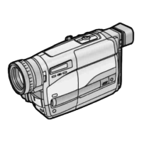
Do you have a question about the Grundig Livance LC 1100 and is the answer not in the manual?
| Sensor Type | CCD |
|---|---|
| Optical Zoom | 3x |
| Digital Zoom | 4x |
| Type | Compact |
| Effective Pixels | 10.1 Megapixels |
| Display Size | 2.7 inches |
| ISO Sensitivity | Auto, 100, 200, 400, 800, 1600 |
| Video Resolution | 640 x 480 |
| Storage Media | SD Card |
| Weight | 120 g |
| Shutter Speed | 8 - 1/2000 sec |
Provides basic service manual information and part ordering procedures.
Notes on differences between RZ9 and RZ10 series camera models.
Comparison of features across different RZ9 and RZ10 camera models.
Procedures for re-installing EEPROM data after replacing the Main C.B.A.
Lists required extension cables and their part numbers for servicing.
Instructions for accessing adjustment modes and connecting test equipment.
Overview of the SERVICE INFORMATION DISPLAY function for quick troubleshooting.
Displays error codes, their conditions, and power off timing for diagnostics.
Steps and safety precautions for inserting the backup button-type battery.
Flowchart detailing disassembly steps, parts, and screw references.
Flowchart for disassembling the lens unit and related circuit boards.
High-level system diagram showing major functional blocks and connections.
Diagram illustrating interconnections between main components and boards.
Detailed block diagram of system control, servo, and power supply circuits.
Block diagram of the camera section, including sensor and processing units.
Block diagram of the video signal processing path.
Schematic for the lens drive motor control and associated circuitry.
Schematic detailing camera analog signal processing and CCD drive.
Schematic for camera digital processing, memory, and OSD.
Schematic of the video signal processing and playback circuits.
Schematic for system control, servo, and power management systems.
Schematic of the audio signal processing and playback circuits.
Schematic of the power supply and voltage regulation circuits.
Schematic for servo control of capstan and cylinder motors.
Schematic for Audio/Video Signal (AVS) output connections.
Schematic of the Black and White Electronic Viewfinder circuit.
Schematic of the microphone unit and remote control sensor.
Schematic for the CCD flex card connecting the sensor to the main board.
Component address information for the Main C.B.A.
Diagram showing the component layout on the Main C.B.A. (component side).
Diagram showing the foil layout on the Main C.B.A. (foil side).
Component and foil side layouts for the Mic Unit circuit board.
Component and foil side layouts for the B/W EVF C.B.A.
Layout diagram for the CCD Flex Card C.B.A.
Exploded view diagram of the VTR Mechanism Section (1).
Exploded view diagram of the VTR Mechanism Section (3).
Exploded view diagram of the Optics and Camera Lens Section.
 Loading...