Do you have a question about the GRUP ARGE SMART S12 and is the answer not in the manual?
Essential safety rules for device handling, cleaning, and troubleshooting.
Guidelines for device disposal and safe installation/operation by experts.
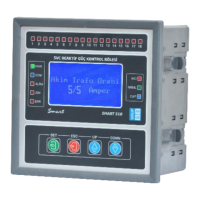
Identifies and describes the LCD screen, indicator LEDs, and control buttons on the device.
Explains the purpose and usage of each control key and their combined functions.
Details key interactions and scenarios for operation and testing.
Illustrates the electrical connections for the SMART S12 model.
Illustrates the electrical connections for the SMART S18 model.
Illustrates the electrical connections for the SMART S18-T model.
Illustrates the electrical connections for the SMART SOG1 and SOG5 models.
Illustrates the electrical connections for the SMART GES1 and GES5 models.
Details the connection and grounding for the toroidal current transformer.
Guides through initial power-up, transformer ratio configuration, and automatic transformer testing.
Details parameters displayed on the operating screen, including power, currents, voltages, and energy.
Explains menu access, Stage Powers, Stage Tests, Transformer Test, Stage Control, and Power Flow.
Details parameters for fine-tuning device behavior and performance.
Configuring transformer ratios, system limits, and LC offset.
Adjusting response times, discharge time, and expert settings.
Covers energy integral, gain multipliers, Modbus, and reset options.
Configuring stage transition time and delay multipliers for capacitors.
Setting up 'off set' stages for loads not seen by the current transformer.
Setting tolerance for ratios and managing offset pin/output.
Setting response resolution, protection multipliers, and generator limits.
Configuring zones, multiplier, DYN value, and transformer ratios.
Managing export/import behavior and compensation modes.
Adjusting screen behavior and power offset multipliers.
Enabling/disabling specific compensation features and modes.
Configuring parallel operation, screen light, and default values.
| Operating Voltage | 12VDC |
|---|---|
| Contact Configuration | SPDT (1 Form C) |
| Contact Rating | 10A 250V AC / 10A 30V DC |
| Coil Power Consumption | 0.36W |
| Insulation Resistance | 100 MΩ min. at 500VDC |
| Mechanical Life | 10, 000, 000 operations |
| Electrical Life | 100, 000 operations at rated load |
| Dielectric Strength | 1500V AC for 1 min |