There are two types of Automatic transfer Switch (ATS):
ATS / QTC – AUTOMATIC TRANSFER SWITCH07.
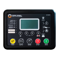
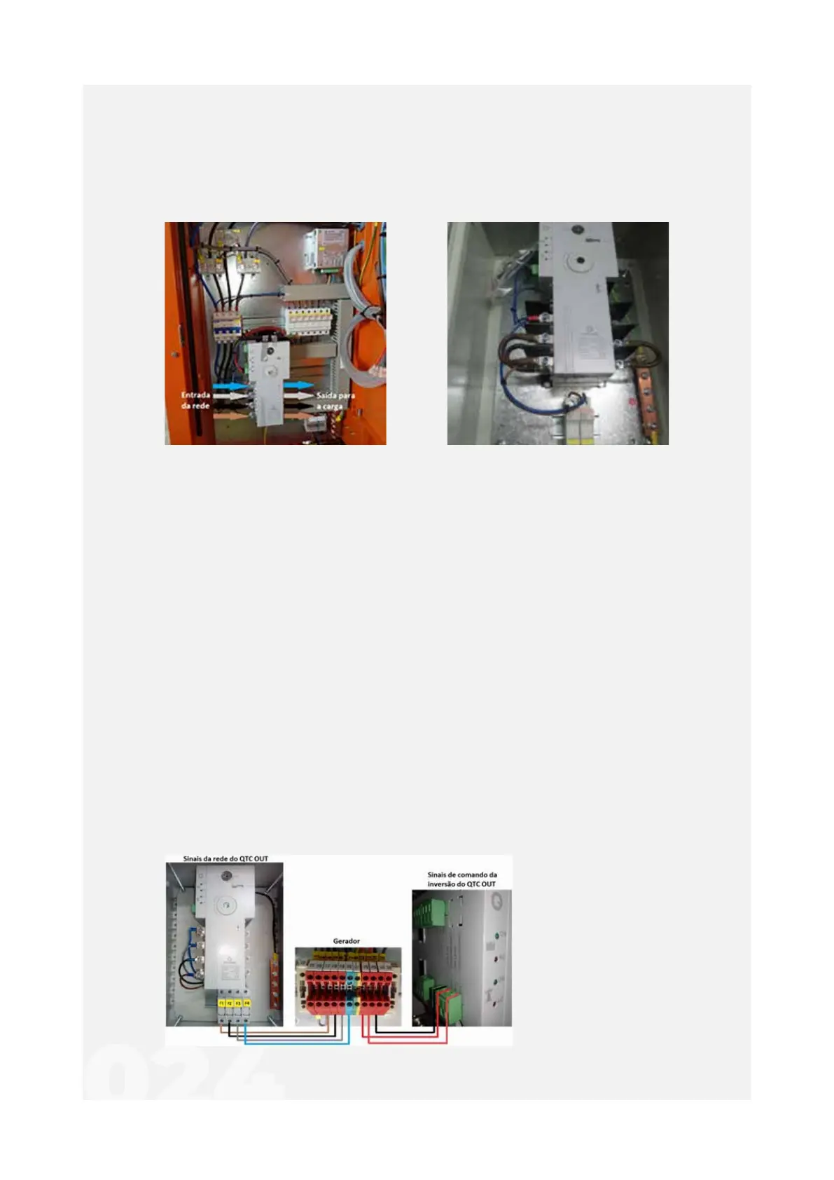
QTC IN ATS IN - located inside the
generator's electrical panel
QTC OUT - located outside
the generator
In the genset controller panel you can find:
1. Source 1 (network);
2. Consumer (item to be loaded);
3. Source 2 (generator);
4. Power ON / OFF Switch;
5. Led access: ATS energized;
6. Led access: Generator will be / is activated;
7. Led access: Automatic mode triggered;
8. Led access: Manual mode triggered;
9. Button for setting Automatic or Manual mode.
If you have requested an ATS/QTC OUT, you must make the respective electrical power
connections:
a) Mains input cables for order of color: blue (neutral), grey (Phase 1), black (Phase 2) and
brown (Phase 3);
b) Output cables for the load, obeying the color order of the input.
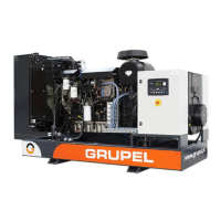
The electrical connections
to be made are:
Gerador X2-21 / QTC F1
Gerador X2-22 / QTC F2
Gerador X2-23 / QTC F3
Gerador X2-24 / QTC F4
Gerador X2-25 / QTC 402
Gerador X2-26 / QTC 404
Gerador X2-91 / QTC 401