EN
9
Description of equipment
components
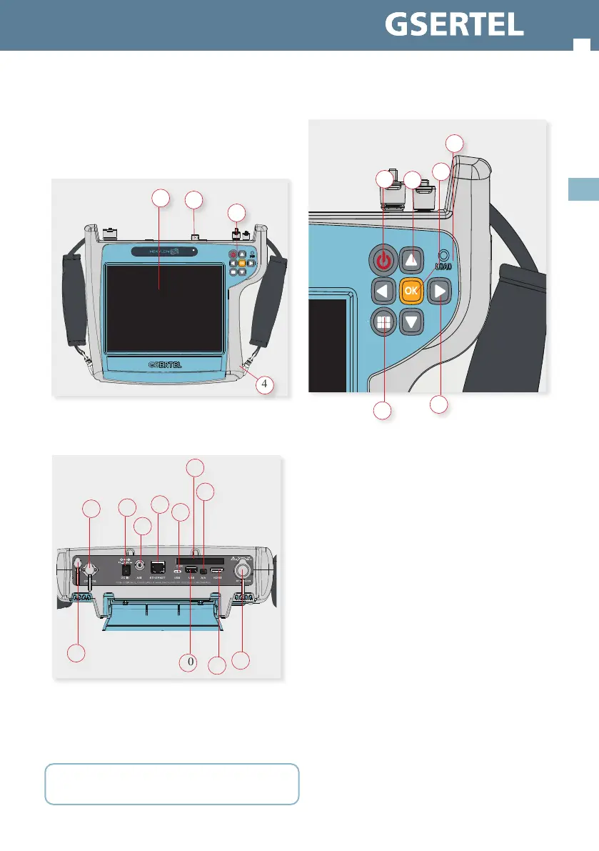
Connectors and controls
1. Touch screen 8” 2. Connectors
3. Keyboard and LED indicators 4. Battery (on the back)
1. F.O. 5. USB-C (future use) 9. HDMI
2. Power connector 6. CAM 10. USB
3. ASI 7. A/V 11. GPS
4. Ethernet 8. RF Input
CAUTION: the USB ports are only for data transmission, not for device
charging
4
1
3
2
8
6
9
11
1
2
3
4
7
5
10
Keyboard
1. Device ON/OFF button: To turn the equipment
o, press and hold for approximately 3 seconds.
Short press to lock/unlock the screen.
2. Menu button: First press-features menu is
shown. Second press-top menu is shown. Third
press-context menu is shown. Fourth press-all
menus are hidden
3. Up/Down buttons: Changes channel
4. Left/Right buttons: Changes screen in multi-
screen features
5. OK button: Short press to accept an option,
and press and hold for more than 10 seconds to
reset the device
6. Powering LED: Indicates if the equipment is
powering an external load
1
2
3
4
5
6
 Loading...