Section 4
4-23
4.3. NANOVOLT DETECTOR CPU OPTIONS
4.3.1. Dip Switches.
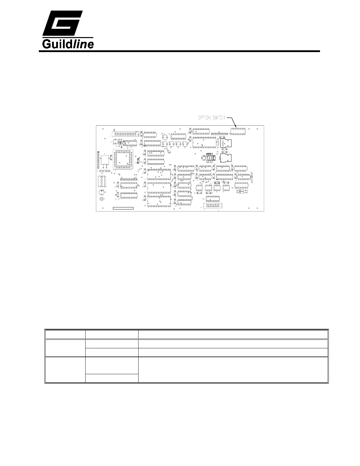
The nanovolt detector has an 8 position piano style switch located as shown in Figure 4-9
on the nanovolt detector CPU PCB. Each of the 8 switches enable or disable an option.
Figure 4-9 : Nanovolt Detector CPU Option Switch Location
4.3.1.1. Option Switch 1 - 50/60 Hz Select.
This option switch must be set to correspond with the nominal line input frequency.
The nanovolt detector processor will read the position of the switch to determine if
the instrument will be operated from a 50 Hz power source or a 60 Hz power
source. This switch must be set correctly for the nanovolt detector to operate
correctly.
4.3.1.2. Option Switches 2 to 8 - ADC Beta.
The ADC Beta value is factory set and should be left as is. The value is 220 + the
value set on the dip switch in binary, shifted to the right by one (0 127). If
switch one is set to 50 Hz the value is (220 +(0 127)) 1.2.
Switch Position Description
1 Closed When connected to 50 Hz line power
Open When connected to 60 Hz line power
2 - 8 2
n
= Closed ADC Beta Value = 220 plus binary value
of switches 2-8 (0127)
0 = Open (if 50Hz multiply value by 1.2)
Table 4-1 : Nanovolt Detector CPU Option Switches
 Loading...