Section 4
4-3
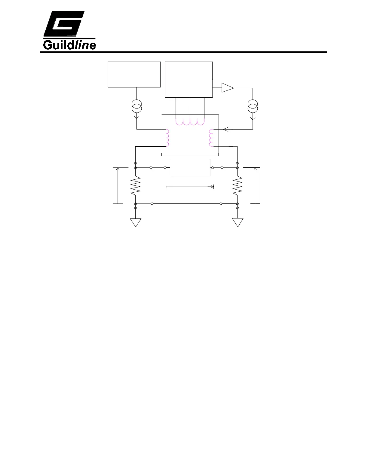
X
P1
C1
Rx
V
C2
P2
Nx
Master PSU
djustment
Manual
Ix
S
Vd
Rs
P1
Detector
Comparator
Current
ASSEMBLY
Null
TOROID
P2
Ns
C1
C2
Vs
Demodulator
and Slave
Modulator
Magnetic
DetectorFlux
Nd
Is
PSU
Figure 4-1 : Direct-Current-Comparator Bridge
Also, by semi-automating the balance of the zero ampere-turn flux condition, using an
electronic closed loop feedback network operating on the flux detector output to drive a
slave power supply for Is, the operator need only make manual adjustments for one effective
bridge balance (null voltage condition), by adjusting the windings in the turns Nx.
4.1.2. The automatic bridge.
A simplified diagram of the automatic direct-current-comparator is shown in Figure 4-2. As
with the bridge of Figure 4-1. it can be seen that two sets of four terminal connection
hardware are provided, one set for the reference resistor and one set for the unknown
resistance. A current (Ix), set under control of the microprocessor, is passed through the
variable turns of winding (Nx) of the comparator and through the unknown resistance (Rx).
The isolated slave current (Is) is generated under microprocessor control, as a linear function
of the number of turns (Nx) and is forced through the fixed slave windings (Ns) and the
reference resistor (Rs). The currents (Is) and (Ix) flowing in the windings (Ns) and (Nx)
respectively generate a net magnetic flux imbalance in the flux detector windings (Nd). This
flux imbalance is proportional to the net ampere-turn error between the two windings [(Is) x
(Ns)] and [(Ix) x (Nx)]. By sensing this imbalance with the sensitive flux detector winding
and an electronic peak detector, a voltage signal is generated proportional to the sign and
magnitude of the ampere-turn error. This voltage is used in a simple closed loop control
configuration to adjust the slave current (Is) to bring the (ampere-turn) error signal to zero.
 Loading...