EXTERNAL CONTROL
183
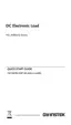
External Trigger Signal
Pins 11 and 12 of the J1 connector are the trigger
signal inputs. The trigger signal is used to resume
a sequence after a pause. This action is useful to
synchronize the execution of a sequence with
another device.
Pin 11 of the J1 connector is internally pulled down
to A COM with an approx. 50kΩ resistor. To use
the trigger input, an active high TTL pulse of 10μs
or more is required.
PEL-3000(H)
Trigger
input signal
Analog
connector
12
11
A COM
A COM
50kΩ
External Control of the Alarm
An alarm can be activated/deactivated using
external control with the J1 connector (pins 10, 12).
When the alarm is activated, an EXT.AL message is
also output. The alarm can be activated by an
external device or by a parallel slave unit.
The alarm is activated by sending a low-level
signal. The operating threshold level is TTL.
Pin 10 is internally pulled up to 5V with a 10kΩ
resistor when open. When closed, pin 10 is pulled
down to the A COM ground level.
 Loading...