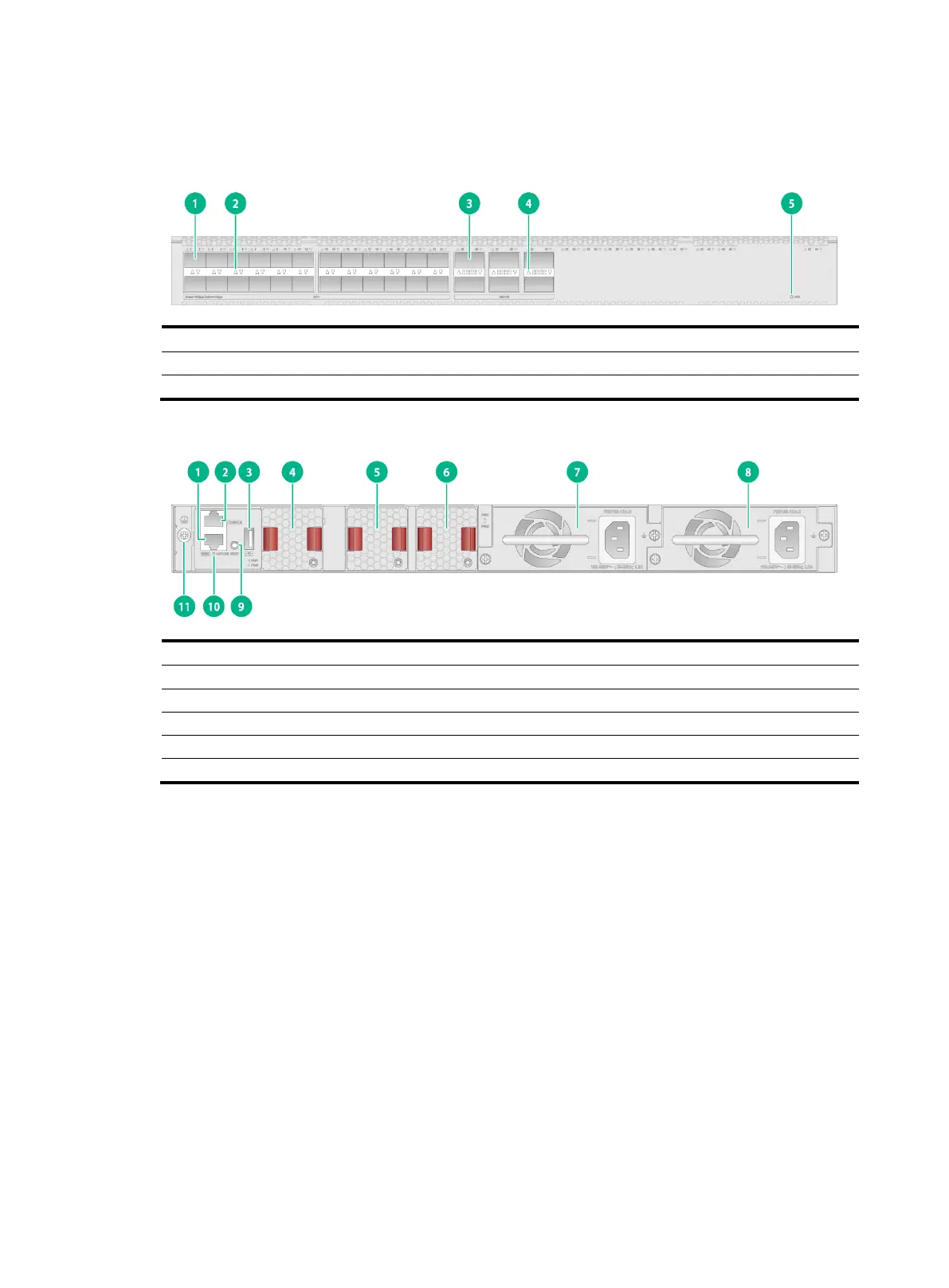
S6520X-30HF-EI & S6520X-30HF-HI
Figure2-9 Front panel
(5) System status LED (SYS)
Figure2-10 Rear panel
(1) Management Ethernet port
(2) Console port (CONSOLE)
(7) Power supply 1 (PWR1)
(8) Power supply 2 (PWR2)
(10) Management Ethernet port LED (ACT/LINK)
The S6520X-30HF-EI and S6520X-30HF-HI switches come with power supply slot PWR1 empty
and power supply slot PWR2 installed with a filler panel. You can install one or two power supplies for
the switch as required. In Figure2-10, two PSR180-12A-B power supplies are installed in the power
supply slots.
The S6520X-30HF-EI and S6520X-30HF-HI switches come with the three fan tray slots empty. You
must install three fan trays of the same model for the switch. In Figure2-10, three LSPM1FANSB-SN
fan trays are installed in the fan tray slots.
The S6520X-30HF-EI and S6520X-30HF-HI switches come with a reset button RESET. You can
press the button to reboot the device.

 Loading...