Do you have a question about the Hach Ultra ORBISPHERE 510 and is the answer not in the manual?
Unpacking the instrument and accessories from the box and packing material.
List of actions to complete the instrument installation process.
Instructions for mounting the instrument on walls or pipes.
Provides overall dimensions for wall/pipe mount instrument models.
Step-by-step guide for physically mounting the instrument on a wall.
Step-by-step guide for physically mounting the instrument on a pipe.
Details on accessing and connecting via the bottom connection panel.
Procedure to lower and remove the cable protection shield.
Instructions on how to open and secure the instrument's front panel.
Instructions for mounting the instrument in a panel.
Provides overall dimensions for panel mount instrument models.
Step-by-step guide for installing the instrument into a panel.
Details on accessing and connecting via the bottom connection panel.
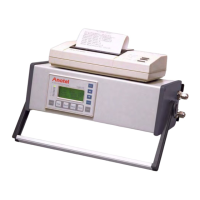
Instructions for setting up the portable instrument.
Provides overall dimensions for portable instrument models.
Instructions for placing and positioning the portable instrument.
Details on accessing and connecting via the bottom connection panel.
Instructions for assembling and wiring connectors.
Detailed steps for wiring cables through waterproof cable glands.
Procedure for attaching an Industrial Ethernet cable to the connector.
Information on the supplied cable for connecting the instrument to a PC.
Instructions for connecting the instrument to the power supply.
Details on the external power supply unit for portable instruments.
Instructions for connecting low voltage instruments to mains power.
Instructions for connecting high voltage instruments to mains power.
Details on connecting cables to the instrument's electronic boards.
Information on connecting sensor cables to the instrument.
Procedure for connecting and disconnecting electronic board connectors.
Details on the connections available on the main board.
Information on EC and TC measurement boards and connectors.
Instructions on how to configure measurement alarm relays.
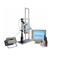
Instructions for installing EC and TC sensors.
Refer to the manual for EC sensor installation, servicing, and maintenance.
Refer to the manual for TC sensor installation, servicing, and maintenance.
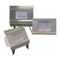
Overview of the instrument's user interface elements.
Details on the 320x240 pixel color touch screen interface.
Explanation of the function keys available on the header bar.
Description of special function keys for portable instrument versions.
Guide to navigating through the instrument's menus and submenus.
Explanation of the rolling list selection mechanism.
Details on using the on-screen virtual keyboard for input.
Procedure for user identification and setting authorization levels.
Explanation of warning messages displayed during instrument operation.
Overview of the instrument's main menu structure and submenus.
Options for selecting between Numeric, Diagnostic, and Statistic views.
Displays numeric measurement values, trends, and temperature.
Provides information useful for troubleshooting instrument issues.
Offers statistical data for process analysis and quality management.
Parameters for customizing the appearance and content of view styles.
Settings to customize the numeric view display parameters.
Settings for configuring the statistic view parameters.
Settings for configuring the diagnostic view parameters.
Configuration settings for the instrument's measurement mode.
Enabling and configuring TPO/TPA calculation for portable instruments.
Selecting between continuous and sample measurement modes.
Selecting the measurement mode (continuous or sample).
Configuration settings for the EC and TC sensors.
Configuration parameters specific to the EC sensor.
Configuration parameters specific to the TC sensor.
Setting thresholds and parameters for measurement alarms.
Configuring filters to flatten measurement curves and reduce noise.
Advanced settings for EC and TC sensors.
Configuring corrections for interfering gases in measurements.
Adjusting parameters for recording and storing measurement data.
Defines the types of calibration performed on the instrument.
Procedure for calibrating EC gas sensors.
Steps to calibrate the sensor to the gas being measured.
Procedure for calibrating TC gas sensors.
Steps to calibrate the TC sensor to the gas being measured.
Information on common calibration errors and their causes.
Calibrating for hydrogen interference in EC sensors.
Calibrating for interfering gases in TC sensors.
Procedure for calibrating the instrument's barometric pressure sensor.
Methods for calibrating the optional external pressure sensor.
Details on how calibration reports are generated and what they contain.
Configuring the snooze function for alarms.
Checking the actual state of alarm relays and analog outputs.
Information on measurement alarm relays and system alarm relays.
Configuring measurement and system relays with standard or custom events.
Manually activating measurement alarm relays for testing.
Manually activating the system alarm relay for testing.
Configuration and behavior of the instrument's analog output channels.
Setting the analog output range and event indication modes.
Configuring the measurement type and output characteristics for each channel.
Procedure for calibrating the instrument's analog output signals.
Testing the calibration of analog outputs by comparing values.
Testing correct operation of peripherals connected to analog outputs.
Setting the characteristics of analog outputs (Mono Linear, Tri Linear).
Configuration settings for the Mono Linear analog output characteristic.
Configuration settings for the Tri Linear analog output characteristic.
Setting the analog output to 'None' disables output and reduces power.
Configuring the instrument for RS-485 simple mode communication.
Details on the format of data available for RS-485 communication.
Practical example demonstrating RS-485 communication setup.
Instructions for configuring PROFIBUS-DP communication.
Steps for installing the PROFIBUS-DP module and related files.
Details on PROFIBUS-DP input/output data formatting.
Using the USB-A port for exporting or importing data.
Enabling and configuring HTTP/TCP-IP for web-based data access.
Overview of the HTTP/TCP-IP web server functionality.
Accessing instrument data via a web browser on a PC.
Procedure for transferring data files via the USB port.
Instructions for installing necessary PC software for data transfer.
Steps for configuring Microsoft ActiveSync® for instrument connection.
Process for uploading and converting report files from the instrument.
Managing user IDs, passwords, and access levels.
Setting up security parameters like session time and user logging.
Adding, editing, or deleting registered instrument users.
Details on the user action log file and its contents.
Overview of saving, using, and transferring product configurations.
Selecting a product from the list for analysis or modification.
Modifying existing product configurations, including gas selection.
Overview of saving and using instrument configurations.
Saving the current instrument configuration settings.
Selecting a previously saved instrument configuration.
Tools for diagnosing sensor status and calibration/service timers.
Checking when the next sensor calibration is due.
Checking when the next sensor service is due.
Diagnostic tool for checking EC sensor's null current measurement ability.
Checking EC measurement board ability for currents and temperatures.
Checking TC measurement board ability for currents and temperatures.
Displaying measured values for V2 and V3 with recommended values.
Selecting the instrument's display language.
Setting the instrument's actual time and date.
Screen adjustment and calibration options.
Adjusting click positions on the touch screen display.
Adjusting the brightness and contrast of the display.
Configuring instrument sounds, including touch sounds and alarms.
Displaying information about the instrument's main and measurement boards.
Information on the instrument model, software version, and ID.
Information on sensor measurement board hardware and software.
Information on sensor model, type, calibration, settings, and behavior.
Displaying real-time clock and portable instrument battery charge levels.
Procedure for Hach Ultra technicians to download software versions.
Procedure to stop and restart the instrument's application.
Enabling or disabling instrument channels when not in use.
Guidance on performing instrument maintenance.
Identifying and understanding instrument events and abnormal conditions.
List of instrument events, their descriptions, and criticality levels.
Guidelines for safely storing, handling, and transporting the instrument.
Overview of the instrument's hardware components.
Explanation of the model number coding system.
Environmental and operational limits for the instrument.
Details on the instrument's power supply options.
General technical specifications of the instrument.
Overview of the instrument's communication capabilities.
Physical dimensions and weight of the instrument versions.
Specifications for analog and digital outputs.
Table detailing user security levels and their associated rights.
Factory default configurations for instrument settings.
List of accessories available for the Orbisphere instruments.
List of spare parts available for the Orbisphere instruments.
Definitions and meanings of various gas units.
Definitions of generic terms and concepts related to the instrument.
| Power Supply | 100-240 VAC, 50/60 Hz |
|---|---|
| Protection Class | IP65 |
| Parameter | Dissolved Oxygen |
| Accuracy | ±1% of reading |
| Operating Temperature | 0 to 50 °C |
| Outputs | 4-20 mA |