9705 - Annex 79 of 82
KSS - March 2006 - Edition 1
HIAC Operator Manual
Annex
Tables and illustrations
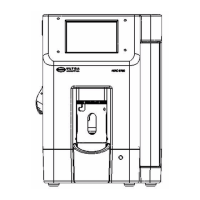
Fig 1-1 : Model 9705 Liquid Particle Counting System.................................... 11
Fig 2-1 : 9705 Particle Counting System ......................................................... 13
Fig 2-2 : Rear View of 9705............................................................................. 14
Fig 2-3 : 9705 Right Side View ........................................................................ 15
Fig 2-4 : Door Open Error Message ................................................................ 17
Fig 2-5 : Main Screen ...................................................................................... 18
Fig 2-6 : Setup Screen..................................................................................... 18
Fig 2-7 : Syringe Settings Screen.................................................................... 19
Fig 2-8 : 9705 Left Side View .......................................................................... 20
Fig 2-9 : Main Screen ...................................................................................... 21
Fig 3-1 : 9705 Icon Bar .................................................................................... 23
Fig 3-2 : Setup Screen..................................................................................... 23
Table 3-1 : Settings Button Functions ................................................................. 24
Fig 3-3 : System Settings Screen .................................................................... 25
Fig 3-4 : Display Settings Tab ......................................................................... 25
Table 3-2 : Display Settings Fields...................................................................... 26
Fig 3-5 : System Settings Screen .................................................................... 26
Fig 3-6 : Sizes Tab .......................................................................................... 27
Fig 3-7 : Syringe Settings Screen.................................................................... 29
Fig 3-8 : System Settings Screen .................................................................... 29
Fig 3-9 : Sound Settings Screen...................................................................... 31
Table 3-3 : Sound Tab Field Descriptions ........................................................... 31
Fig 3-10 : Tilt Bottle Dock .................................................................................. 32
Fig 3-11 : Remove Bottle Guide ........................................................................ 33
Fig 3-12 : Insert Needle Removal Tool.............................................................. 33
Fig 3-13 : Seat the Tabs .................................................................................... 34
Fig 3-14 : Remove the Needle........................................................................... 34
Fig 3-15 : Tilt Bottle Dock .................................................................................. 35
Fig 3-16 : Remove Bottle Guide ........................................................................ 36
Fig 3-17 : Insert Needle Removal Tool.............................................................. 36
Fig 3-18 : Seat the Tabs .................................................................................... 37
Fig 3-19 : Remove the Needle........................................................................... 37
Fig 3-20 : Turn the Handle Counterclockwise ................................................... 38
Fig 3-21 : Align the Adapter............................................................................... 38
Fig 3-22 : Seat the Adapter ............................................................................... 39
Fig 3-23 : Install the Bottle Guide ...................................................................... 40
Fig 3-24 : Ready for LVA Connection................................................................ 40
Fig 3-25 : Lab Stand Assembly ......................................................................... 41
Fig 3-26 : Connect the LVA Fitting to the Sampling Probe................................ 42
Fig 3-27 : Connect the LVA Fitting to the Probe................................................ 43
Fig 3-28 : Large Volume Adapter Assembly...................................................... 43
Fig 3-29 : Ferrule Installation............................................................................. 44
 Loading...