81
Optional device installation
Figure 27 shows the wiring of the pH probe in the pre-amplifier junction box. Since the pH
reading needs to compensate for temperature variation, a temperature sensor is built into
every pH electrode. The pH probe consists of five wires, three for the pH probe and two
for the temperature sensor.
Stray electrical currents are sometimes found in wastewater streams. These stray
electrical currents can affect the pH readings. In the case of stray electrical currents, a
grounded pH probe is required (Figure 28).
Table 8 pH connector pin assignments (J-3)
Pin Signal Description Wire Color
A+5 V dc White
Bground Blue
C reference Yellow
DpH/ORP Black
E -5 V dc Red
FRTD Green
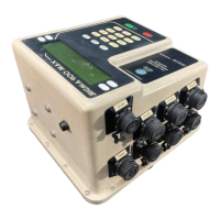
Figure 27 pH probe wiring to junction box (un-grounded)
1 Yellow 4 pH
2 Green 5 Glass
3 Clear 6 Red
Goodnal STP ST041 Pre Treatment (Sigma 900 MAX All Weather Refrigerated Sampler) Vendor Manual
 Loading...