99
Communication setup
8.4.1 Alarm relays connection
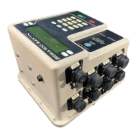
Relay junction box
Required relay box is an alarm relay box assembly with a 10-ft long cable with a 6-pin
connector on one end and a relay box on the other end (Figure 32).
1. Choose Normally Closed (NC) or Normally Open (NO) connections.
2. Hook into the terminal strip one wire in the common (COM) and the other in the
connector with the preferred signal.
Table 17 Relay connector on the sampler (J17)
Pin Signal Description Wire Color
A+12 V dcRed
B Relay #1 Yellow
C Relay #2 Black
D Relay #3 Red
E Relay #4 Green
Figure 31 Relay pin connections
Table 18 Relays
Connector Relay
J2 1
J3 2
J4 3
J5 4
Goodnal STP ST041 Pre Treatment (Sigma 900 MAX All Weather Refrigerated Sampler) Vendor Manual
 Loading...