Project planning and mounting
Securing escape and emergency routes
U-PW powerway System Manual 67
04.04 Securing escape and emergency routes
Securing escape and emergency routes
When planning and installing low-voltage switchgear, the necessary escape and emergency routes
must be observed. Particular attention must be paid to the use of doors on the enclosures: The doors
must always close in the escape direction as they will block the escape route otherwise. Withdrawable
module units can also restrict escape and emergency routes.
See the information in DIN VDE 0100-729:
– Opening direction of enclosure doors and direction of escape
– Minimum distances for doors with locking mechanisms
– Minimum distances on withdrawable circuit breakers
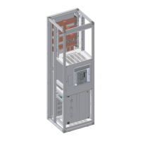
04.05 Information on mounting enclosures in the installation position
Mounting in the installation position
Refer to the following information on setting up and mounting the installed enclosures.
See also the unimes H System Manual.
Requirements
– Level and load-bearing installation surface
– In case of unevenness, use U profiles or I profiles or the optionally available base levelling set
mes-NIV.
– Clean and dry installation site; if necessary, apply a dust protection floor coating to the floor.
Preparing the site
Prepare the site of the switchgear and controlgear assembly:
Ensure a level surface. The maximum tolerance to ensure safe mounting is +/- 2 mm/m. In case
of unevenness, use suitable compensation material.
Maximum tolerance: +/- 2 mm/m
Observe the weight load on the surface at the site. If an intermediate floor is used for supporting
the connection cable, it must be designed to support the weight of the enclosure, including all
equipment and devices.
Take the permitted bending radii for cable entries and cable feeds into account.
The ambient temperature must be within the range of the enclosure operating conditions, the in-
stalled devices and the routing conditions for the equipment.
Ensure adequate lighting of the work environment.
 Loading...