Project planning and mounting
Sequence of assembly steps
68 U-PW powerway System Manual
Maintaining free spaces
Maintain the required free spaces (minimum specifications):
– Minimum spacing of cabinet surface to the ceiling: 500 mm
– Minimum passage height below covers or enclosures: 2000 mm
– Minimum gangway width in front of the switching cabinet: 700 mm (in front of switching cabinets
with withdrawable parts in the isolated position: 600 mm). With distribution units whose doors
open against the escape direction, the necessary escape route of 500 mm must also be available
when the doors area opened at 90°. If necessary, wider gangways must selected so that cabinet
doors can be opened and withdrawable parts can be completely removed.
– The width and dimensions of the access points must be suitable at all times
– For operation and maintenance,
– In emergencies,
– As an emergency exit and
– For transporting equipment.
04.06 Sequence of assembly steps
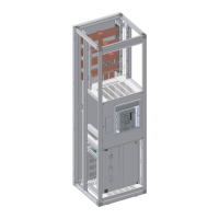
Installation order when assembling a powerway enclosure
powerway enclosures are pre-assembled in the factory (depending on the ordered scope of supply)
before being finally assembled by the customer according to their requirements.
Factory pre-assembly:
Basic enclosure
Floor plate in busbar space
Additional depth support
Vertical upright
Frame covers (from Form 2b)
Extended partition (polycarbonate, from Form 2b)
For the efficient installation of a powerway enclosure by the customer, the following order of assembly
has proven effective.
Customer assembly steps:
Dismantle the front reduction (if its pre-assembly was ordered)
Assemble H-SaS supports
Assemble complete F-SaS support and copper busbars
Install copper busbars in H-SaS
Mount compact ACB on support frame
Install H-SaS/ACB and ACB/H-SaS copper connection or cable connection
Install horizontal and vertical partitions
Install univers N control compartment or extended partitions (transparent plates)
Install F-SaS copper busbars in F-SaS support
Install copper connection lugs between F-SaS and H-SaS
 Loading...