58
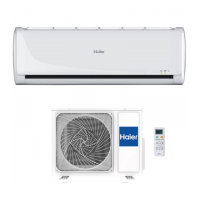
Domestic air conditioner
1. Insert from outside the room cable into left side of the wall
hole, in which the pipe has already existed.
2. Pull out the cable on the front side, and connect the cable
making a loop.
When connecting the cable, confirm the terminal number of indoor and
outdoor units carefully. If wiring is not correct, proper operation can not
be carried out and will cause defect.
Insert the cable from the back
ƽ
side of the unit, then pull it out
on the front side.
Loosen the screws and insert
ƽ
the cable ends fully into
terminal block, then
tighten the screws.
Pull the cable slightly to
ƽ
make sure the cables have
been properly inserted and
tightened.
After the cable connection,
ƽ
never fail to fasten the connected cable with the
wiring cover.
When connecting the cable after installing the indoor unit
When connecting the cable before installing the indoor unit
Note:
1. If the supply cord is damaged, it must be replaced by the manufacturer or its
service agent or a similar qualified person. The type of connecting wire is
H05RN-F
or H07RN-F.
2. If the fuse on PC board is broken please change it with the
type of
3. The wiring method should be in line with the local wiring standard.
4. After installation, the power plug should be easily reached.
5. A breaker should be incorporated into fixed wiring. The breaker should be
all-pole
switch and the distance between its two contacts should be not less
than 3mm.
T.3.15A/250VAC (Indoor).
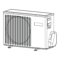
To Outdoor unit
Model
Connecting wiring
4G0.75mm
2
4G0.75mm
2
4G0.75mm
2
AS07GS2ERA
AS09GS2ERA
AS12GS2ERA
AS18GS2ERA
AS24GS2ERA
The power source must be exclusively used for air
ƽ
conditioner.
In the case of installing an air conditioner in a moist place,
ƽ
please install
an ea
For installation in other places, use a circuit breaker as far
ƽ
as possible.
Pipe cutting is carried out with a pipe cutter and burs must be removed.
After inserting the flare nut, flaring work is carried out.
Power Source Installation
Cutting and Flaring Work of Piping
Flare tool for R410A Conventional flare tool
Clutch-type clutch-type(Rigid-type) Wing-nut type (Imperial-type)
A 0~0.5mm 1.0~1.5mm 1.5~2.0mm
rth leakage breaker.
Lean
Damage of flare Partial Too outside
Correct Incorrect
On Drainage
It becomes
high midway.
The gap with the
ground is too small.
There is the bad
smell from a ditch
It waves.
The end is imm-
ersed in water.
Please install the drain hose so as to be downward slope without fail.
Please don’t do the drainage as shown below.
ƽ
ƽ
Please pour water in the drain pan of the indoor unit, and
ƽ
is carried out surely to outdoor.
In case that the attached drain hose is in a room, please
ƽ
apply heat
insulation
to
Less than
5cm
confirm that
drainage
it without fail.
Crack
Indoor unit
Check Items for Test Run
Gas leak from pipe connecting?
Heat insulation of pipe connecting?
Are the connecting wirings of indoor and outdoor firmly
Is the connecting wiring of indoor and outdoor firmly fixed?
Is drainage securely carried out?
Is the earth line securely connected?
Is the indoor unit securely fixed?
Is power source voltage abided by the code?
Is there any noise?
Is the lamp normally lighting?
Are cooling and heating (when in heat pump) performed normally?
Is the operation of room temperature regulator normal?
Please kindly explain to our customers how to
operate
through the instruction manual.
inserted to the terminal block?
Ƶ
Put check mark
in boxes
C ode
indication
Tro uble de scription Analyze and diagnose
E1
Indo or fan m otor
m alfu nction
E2
H eat-exch ang e
se nso r failure
E4
Indo or E E P R O M
error
Faulty E EP R O M data;
Faulty E EP R O M ;
Faulty P C B ;
E7
C om m unica tion
fault betw een
indoor and outd oor
un its
Indo or u nit- o utdoor unit s ig nal
trans m iss ion erro r due to w iring
error;
Faulty PC B ;
E14
Indo or fan m otor
m alfu nction
O p eration halt due to b reaking
of wire in side the fa n m oto r;
O p eration halt due to b reaking
of the fan m otor lea d w ires ;
D ete ction error du e to faulty
indoor unit P C B ;
Faulty connector c onn ectio n;
Faulty therm istor;
Faulty PC B ;
Flare tooling die
1.Cut pipe
2.Remove burs
3.Insert the flare nut
4.Flare pipe
ƽ
ƽ
On Drainage
Check for Installation and Test Run
AS24GS1/2ERA 1U24GS1ERA-SM Introduction
 Loading...