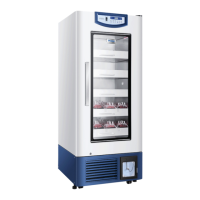
5. Standing
Do not switch on the power after the refrigerator is placed, leveled and cleaned. Switch on the
power after it is put on standing for more than 24h, to ensure normal performance of refrigerator.
6. Installation of the Handle
Handle installation of products shall be conducted
in thefollowing steps:
①. Place downward the handle-end with a hole;
②. Align the handle and handle guide on door;
③. Uphold the handle after the handle is locked
with the handle guide;
④. Use bolt to fix the handle from bottom after tight
installation of the handle.
36
9
1
3
2
4
Circuit Diagram(HXC-1308/1308B)
CN2
1
L
N
2
L
N
t
GND
+12V
L N
t
1
L
N
2
L
N
Power panel
Power line
L
N
E
Condensate fan
Compressor
Defrosting heating strip
Main control panel
Internal fan
Display panel
Sensor
Defrosting
Control
Lower temperature
Upper temperature
Alarm
VCC
GND
Heating strip at the cabinet outlet
Heating strip of center sill
Door heating transformer
Door heating strip 1
Temperature recorder
LED drive model
Lamp switch
USB drive panel
USB port
Reserved network interface
Wiring terminal 2
Double-throw switch
Press wiring terminal box
Power line terminal box
Connection to electric
control cabinet enclosure
Door heating strip 2
Door heating transformer
Wiring terminal 1
Battery switch
Wiring terminal 3
Connection to electric
control cabinet enclosure
Remote alarm port
Filter
High temperature
prevention
thermostat
C
H
L
J5
CN2
N
L
CN1
NO
COM
NC
CN2
CN1
CN7
CN6
CN5
NO
COM
NC
CN1
CN2
CN11
16V
BAT-
BAT+
BT1
GND
CN3
CN1
GND
16V
CN3
FAN
L
N
K2
K3
NC
NC
COM
COM
NO
NO
HTR
Roof-contacted
board
Door switch
door
Connected to
bottom board
of compressor

 Loading...