36
5. Standing
Do not immediately power up the refrigerator after it is installed. Let the unit stand still for 24 hours
and then power it up to ensure the unit works properly.
7. Install handle (HYC-390F/HYC-610/HYC-940F)
a.Place the end
of handle with a
hole facedown.
b.Align the handle with
the holder on the door.
c.Raise the handle
after securing the
handle and holder.
d.Use screws to fasten
the handle at the bottom.
1
2
3
4
6. Installation of Shelves and Label strip
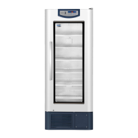
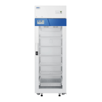
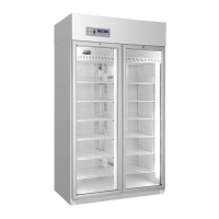
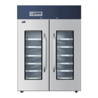
HYC-260/360/610/890/940/940F
HYC-290/390/390F
After mounting the shelf and label strip, place them on the
liner plate slot at the appropriate distance.
Take out the shelf, label strip and rack fastener from the
refrigerator. Fix the shelf fasteners on the liner plate at the
appropriate distance and height. After mounting the shelf
and label strip, place them on the shelf fastener and ensure
the shelf is placed firmly.See Pic. 1 (see Pic. 2 for HYC-610、
HYC-890);
Pic.1
Pic.2
9
Circuit diagram(HYC-610)
CN2
Cooling fan
Compressor
Defrosting heating strip
CN2
CN1
CN3
CN11
BT1
BAT+
BAT-
Main control panel
CN5
Internal fan
Display panel
CN2
CN3
Sensor
Alarm
Defrosting
Control
Lower temperature
Upper temperature
VCC
GND
Heating strip at the cabinet outlet
CN1
t
Door heating strip
Door heating transformer
CN1
J5
L
N
USB drive board
CN1
16V
GND
16V
GND
CN7
Wiring terminal
Battery switch
Power line
Live wire
Null wire
Earth wire
Double-throw switch
Lamp switch
C
H
L
High
temperature
prevention
thermostat
C
H
L
Low temperature
prevention
thermostat
Power panel
N
L
FAN
HTR
NC
NC
NC
NO
NO
NO
K3
K7
K4
CN5
CN4
CN2
CN4
USB
PRINT
Printer communication interface
CN4 and CN5 are both LED power supply interfaces.
Temperature recorder (optional)
LED lamp bank
GND
+12V
Note: Cables at terminal C and terminal
L of the low temperature prevention
thermostat are exchangeable.
CN6
NO
COM
NC
NO
COM
NC
Remote alarm port
Filter
Grounding
Grounding
door
Door switch
Switch
 Loading...