Preparation and installation
See ERRS CP2 technical specifications and ERRS CP2 wiring diagram for detailed installation
information for the ERRS CP2 control system.
Control Panels
The ERRS CP2 control panels shall be set up in a protected position with respect to environmental
protection, mechanical damage and unintended activation from unauthorized persons. An ERRS
CP2 Control Panel set up on deck shall be mounted in an outer protective enclosure (the outer
enclosure will serve as an environmental protection and also as protection against unintended
activation).
Never do any machining to the ERRS CP2 enclosure. This will void the guarantee!
The ERRS CP2 control panel (front panel and bottom section of enclosure) must always be
mounted together to give the correct environmental protection.
If the control panel enclosure during the installation is left without cables connected; seal off the
holes of the cable outlets in order to avoid water or dirt to get inside the box.
When the installation is finished all holes in the ERRS CP2 enclosure shall have EMC cable glands
or sealing plugs installed. There shall be no openings into the enclosure!
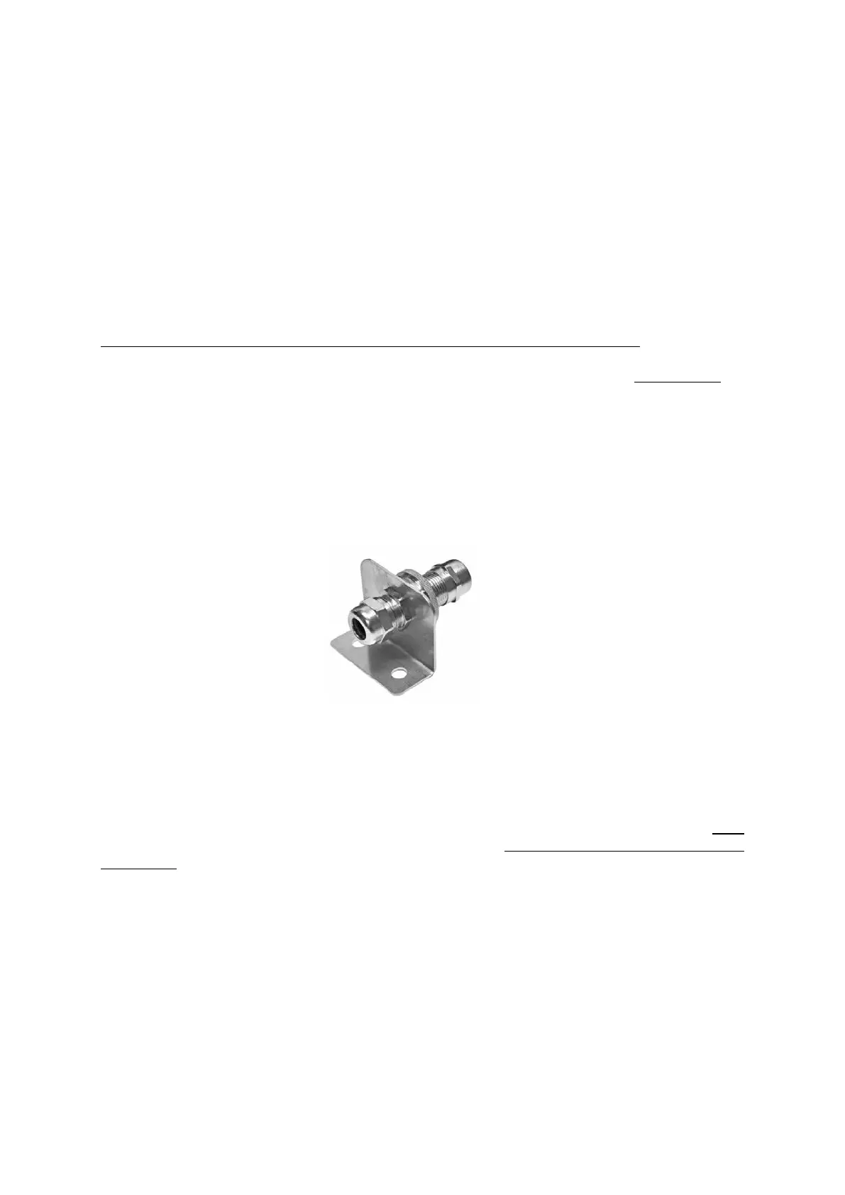
GROUND CONNECTIOON DEVICE M20
Part no: HM-0730 included in the delivery
(Larger size is available: HM-0735)
Each control panel has to be connected to ships ground. The GROUND CONNECTION DEVICE shall
be used for the ground connection of the ERRS2 system. Not to use the device will void the
guarantee! The device is designed to ensure a good permanent electrical connection of the control
panel enclosure to the ships ground. The device is available in two sizes for different cable
diameters. The device can be put on any of the connected cables but make sure that the selected
cable is a cable that has its screen connected to the ERRS CP2 enclosure in its EMC cable gland!
The device shall be mounted close to the ERRS CP2 control panel, see wiring diagram for details.
If there is more than on ERRS CP2 control panel connected together in a network each control
panel shall have its own Ground connection device.
 Loading...