Figure 36
Figure 38
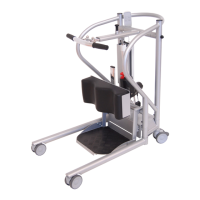
Figure 37
14 HANDICARE 2000 SIMPLICITY / STYLE INSTALLATION MANUAL
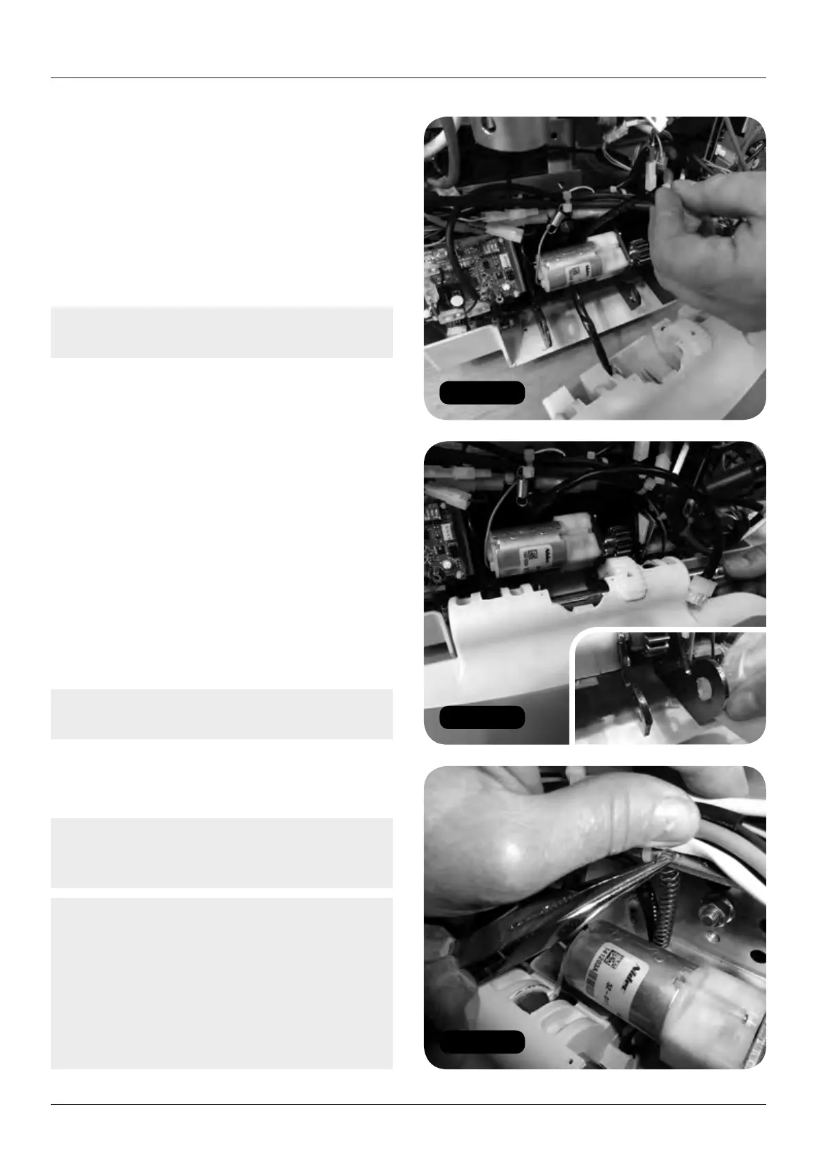
Power pack and footplate
Powered (motor) footplate
a Remove the footrest assembly from the
footrest kit box. Loosen the screw and
remove the shaft from this assembly.
b Feed the footplate loom and spring around
the back of the motor (Figure 36).
c Attach the footrest to the power pack
(Figure 37).
Note: Lubricate the three pivot points and
shaft with HTEP grease (food safe grease).
d Attach the spring to the main chassis
bracket (Figure 38).
e Attach the connector (Figure 39).
6 Fit the batteries (footplate accessories kit)
(Figure 40).
7 Connect the dummy seat toggle looms:
a Driving toggle 8 way connector (Part No.
181001.50083) and conversion loom
(SIM22900) – seat, direction, key switch
and swivel (can only be fitted one way)
(Figure 41).
b 2.5mm battery link (Part No.
181001.52036) across the flying battery
leads – red link wire (Figure 42).
Note: Ensure that this connection is not
earthed as it will blow a fuse.
8 Taking care not to damage the charge
contacts, drive the power pack on to the
track using the driving toggle.
Note: Ensure that the top and bottom trunnions
are correctly engaged to the corresponding
teeth on the top and bottom track (Figure 43).
Note: If the power pack is loaded without
corresponding engagement of the top and
bottom trunnions; and the power pack is
operated it will cause permanent damage to
the power pack. Figure 44 shows how an
incorrectly loaded power pack will appear.
If this occurs a new power pack MUST
be ordered as a matter of safety.