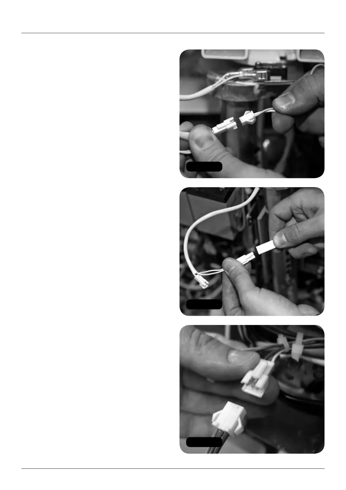
Figure 77
Figure 78
Figure 79
26 HANDICARE 2000 SIMPLICITY / STYLE INSTALLATION MANUAL
Electrical connections Style seat (manual)
Electrical connections
Style seat (manual)
Items required: Tools required:
• None • None
1 Make seat and footplate electrical connections:
a Connect the power switch (2 x red).
b Connect the diagnostic display
(red, black and yellow).
c Connect the key switch loom from the power
pack (orange and green) to the swivel switch
loom connector (2 x white). (Figure 77).
d Connect the seat to the swivel switch loom
connector (white) (Figure 78).
e Connect the toggle loom
(orange, blue and green) (Figure 79).
f Connect the infra-red receivers on the left
and right sides of the pack (blue sleeved).
Powered footplate only
g Connect the powered footplate looms
(twin yellow) (Figure 80).
h Connect the motor cables (red and black)
as per diagram on page 52.
2 Connect the earthing terminal (black)
to the pack and secure with the nut
(Figures 81 and 82).
3 Connect the main seat loom (brown and pink)
to the chassis loom (red and pink) – two black
connectors. (Figure 83).
4 Test the function of the powered features,
including the toggle (see pages 39-41).
5 Replace and refit the pack front cover
(Figure 84).