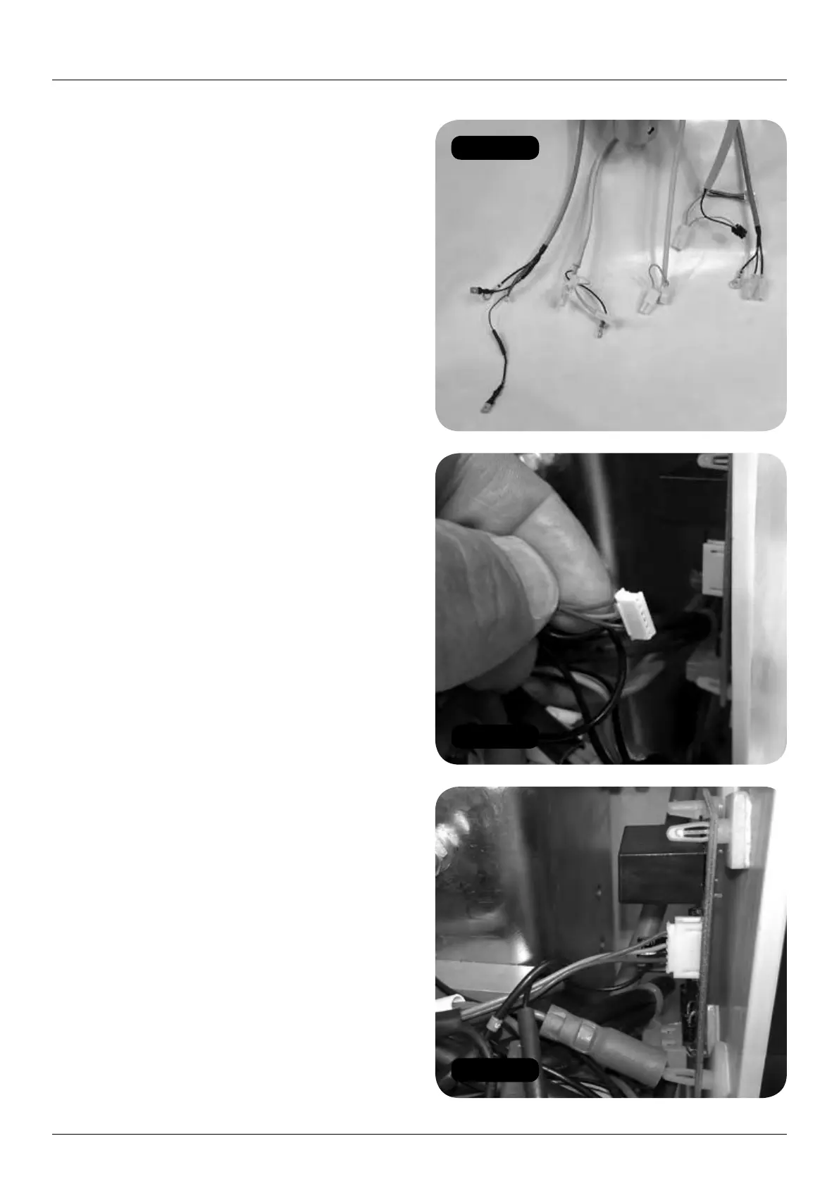
Figure 93
Figure 94
Figure 95
30 HANDICARE 2000 SIMPLICITY / STYLE INSTALLATION MANUAL
Electrical connections Style seat (powered)
Electrical connections
Style seat (powered)
Items required: Tools required:
• None • None
1 You now have five seat cables to connect
to the chassis (Figure 93).
2 Starting with the motor connector, connect
to the in-line PCB. Make sure the flat surface
of the connector is facing the outer edge of
the PCB (Figure 94).
3 Gently push the motor loom connector into
the in-line PCB (Figure 95).
4 Connect the motor loom earth to the chassis
earth stud (Figure 96).
5 Connect the manual swivel over-ride loom
to the motor loom (4 x Green 5) (Figure 97).
6 Connect the manual swivel over-ride loom
earth to the chassis earth stud (Figure 98).
7 Seat Loom 1. Connect earth to chassis earth
stud and secure with nut (Figure 99).
8 Make seat and footplate electrical connections:
a Connect the power switch (2 x red).
b Connect the diagnostic display
(red, black and yellow).
c Connect the key switch loom from the
power pack (orange and green) to the
swivel switch loom connector (2 x white).
(Figure 100).
d Connect the seat to the swivel switch loom
connector (white) (Figure 101).
e Connect the toggle loom (orange, blue and
green) (Figure 102).
f Connect the infra-red receivers on the left
and right sides of the pack (blue sleeved).