Do you have a question about the Hans Grohe MyFox 13165000 and is the answer not in the manual?
| Color | Chrome |
|---|---|
| Temperature limitation adjustable | Yes |
| Non-return valve | Yes |
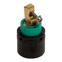
| Thermostat cartridge | Yes |
| Model Number | 13165000 |
| Brand | Hansgrohe |
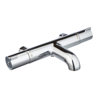
| Series | MyFox |
| Thermostatic | Yes |
| Hand Shower Included | No |
| Center distance | 150 mm |
| Operating pressure | 0.5 - 10 bar |
| Installation Type | Wall-mounted |
| Water Pressure | 1 - 10 bar |
| Warranty | 5 years |
Wear gloves during installation to avoid crushing and cutting injuries.
Product is intended solely for bathing and body cleaning purposes.
Individuals with physical, mental, or sensory impairments require supervision.
Use is prohibited for persons under the influence of alcohol or drugs.
Ensure equal pressure for hot and cold water supplies.
Inspect product for transport damage before installation.
Install, flush, and test pipes and fixture according to applicable standards.
Observe applicable plumbing codes in respective countries.
Product is not designed for use with steam baths.
Thermostatic mixer connections require regular testing after installation.
The maximum operating pressure is 1 MPa.
The recommended operating pressure is between 0.1 and 0.5 MPa.
The test pressure is 1.6 MPa (equivalent to 10 bar or 147 PSI).
Maximum allowed hot water temperature is 70°C.
The recommended hot water temperature is 65°C.
The standard center distance for connections is 160 mm.
Connections are M 26x1,5 with cold on the right and hot on the left.
Thermal disinfection is possible up to 70°C for 4 minutes.
The product includes safety features against backflow.
Product is exclusively designed for use with drinking water.
Do not use silicone sealants that contain acetic acid.
Check and adjust thermostat output temperature if measured differs from set temperature.
Set a desired maximum temperature, e.g., 42°C, to prevent scalding.
Check check valves regularly per DIN EN 1717 and local regulations (at least annually).
Periodically turn thermostat from hot to cold to ensure smooth operation.
Diagram illustrating the flow path to the shower outlet.
Diagram illustrating the flow path to the tub outlet.
Addresses issues of low water flow, checking pressure and filters.
Resolves crossflow issues due to dirty or leaking backflow preventers.
Corrects spout temperature discrepancies by adjusting the thermostat.
Addresses inability to regulate temperature, often due to calcified thermo cartridge.
Resolves dripping from shower or spout by cleaning or replacing shut-off units.
Illustration showing the initial step of securing the mounting plate.
Diagram for aligning and attaching the fixture to the mounting plate.
Visual guide for tightening the connections on the fixture.
Illustration of the final steps in the installation process.
Shows tightening the nuts of the installation plate according to manufacturer's instructions.
Illustration of measuring water temperature with a thermometer.
Diagram showing the disassembly of a thermostat component.
Visual guide for removing the thermostat cartridge.
Illustration showing access to the thermostat's adjustment mechanism.
Diagram for adjusting the temperature setting using a tool.
Illustration showing the reassembly of the thermostat components.
Illustration showing disassembly to access the safety function adjustment.
Diagram showing how to set the desired maximum temperature.
Illustration of checking the set temperature with a thermometer.
Visual guide for adjusting the safety stop mechanism.
Illustration showing reassembly and re-checking the temperature.
Diagram illustrating the final reassembly of the thermostat.
Illustration showing the initial state for engaging the EcoStop function.
Diagram showing disassembly to access the EcoStop mechanism.
Visual guide for engaging the EcoStop for water saving (e.g., 10 l/min).
Illustration showing how to adjust the EcoStop mechanism.
Diagram for securing the EcoStop setting.
Illustration showing the final state after engaging EcoStop.
Illustration of initial connection and tightening using a wrench.
Diagram showing the fixture being attached to the wall plate.
Visual guide for securing the fixture with screws.
Illustration of connecting the water supply hoses.
Diagram for the final securing of the fixture.
Illustration showing the final attachment to the wall plate.
Illustration of securing the thermostat unit.
Shows final tightening of nuts on the installation plate per manufacturer's instructions.
Details regarding product certification and model numbers.
Demonstrates adjusting shower flow from approximately 50% to 100%.
Illustrates selecting cold water flow or hot water flow (>40°C).
Shows how to close or shut off the water flow.
Demonstrates adjusting shower flow from approximately 50% to 100%.
Illustrates selecting cold water flow or hot water flow (>40°C).
Shows how to close or shut off the water flow.
Detailed dimensional drawings for the MyFox 13165000 model.
Detailed dimensional drawings for the MyFox 13164000 model.
Flow rate graph for MyFox 13165000, showing flow vs. pressure.
Flow rate graph for MyFox 13164000, showing flow vs. pressure.
Exploded view and part numbers for MyFox 13165000.
Exploded view and part numbers for MyFox 13164000.
Information and recommendations for cleaning the product.
Details regarding the product warranty period.
Hansgrohe contact details for support and inquiries.