Do you have a question about the Hanshin Machinery GRH 3 series and is the answer not in the manual?
| Brand | Hanshin Machinery |
|---|---|
| Model | GRH 3 series |
| Category | Air Compressor |
| Language | English |
Explanation of model designation including output and cooling type.
Cautions for installation, operation, repair by competent engineers, and avoiding misuse.
Explanation of warning, caution, and prohibition marks for safe operation and trouble avoidance.
Specific cautions for GRH3-20A, 25A, 30A, 35A, 50A models regarding discharge, electric shock, scalds, and rotation.
Specific cautions for GRH3-75A, 100A models regarding discharge, electric shock, scalds, and rotation.
Common safety rules, including understanding the manual, wearing safety devices, and expert handling of settings.
Guidelines for selecting installation locations and precautions to prevent damage and ensure proper operation.
Rules and precautions for safe and proper electrical wiring, including circuit breakers and grounding.
Safety precautions during compressor operation, including stopping procedures, high pressure, and flammable materials.
Precautions to take when stopping the compressor, including for long periods.
Safety precautions related to maintenance, including pressure, power, and part replacement.
Visual identification of front and rear external components of the compressor.
Identification of internal components within the compressor unit.
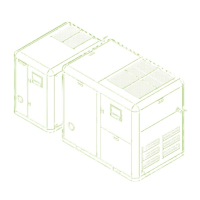
Visual identification of front and rear external components for GRH3-75A and 100A models.
Identification of internal components within the compressor unit for GRH3-75A and 100A models.
General wiring precautions, lead-in power cable connection, and electric cable specifications.
Specifications and procedures for proper grounding of the compressor.
Instructions for installing a suitable circuit breaker and performing routine electrical checks.
Procedure to check motor insulation resistance using a tester.
Guidelines for power facilities, including cable thickness, grounding specifications, and circuit breaker capacity.
Table of circuit breaker capacities suitable for different compressor models and power supplies.
How to check product specifications and for any damage during transportation.
Methods and precautions for transporting the compressor using forklifts or cranes.
Guidelines for selecting installation locations and precautions to prevent damage and ensure proper operation.
Warnings against installing in unsuitable environments like dusty, wet, or harmful gas locations.
Guidelines for proper ventilation of the compressor room to prevent overheating and ensure optimal performance.
Instructions for installing ventilators and ducts to ensure adequate airflow and noise reduction.
Precautions and best practices for connecting air pipes to the compressor for optimal performance and maintenance.
Precautions for operating and stopping compressors in parallel configurations.
Importance of the receiver tank, its drain pipe, and capacity recommendations.
Overview of the Micom controller, its display, buttons, and indicator lamps.
Diagram showing the rear view of the Micom controller and its connections.
Explanation of the analogue controller used in GRH3-20A to 35A models, its functions, and indicators.
Detailed steps for turning on, operating, stopping, and remotely controlling the compressor.
How to remotely control the compressor's operation and stop functions via external buttons.
How to remotely control load and no-load operation modes using specific terminals.
Step-by-step guide for the initial startup and regular operation of the compressor.
Procedures for routine operation checks, including visual inspection, oil level, and pressure settings.
How to set and operate the compressor based on a pre-defined schedule.
Detailed instructions for remote operation, stop, and status monitoring using external contacts.
Setup and functionality of the Micom-based remote monitoring system for compressor management.
Overview of computer-based remote monitoring and control systems for multiple compressors.
Explanation of the Micom display screens and navigation for configuration and operation monitoring.
How to set up, check, and interpret various operation data displayed on the Micom controller.
Guide to setting and modifying operational parameters such as pressure and time settings.
Explanation of protective devices and a list of LCD messages for alarms and trips.
Troubleshooting guide for common issues like motor overloads, high temperature, and reverse phase.
Causes and measures for abnormal temperature/pressure sensor readings and signal trips.
Flowchart to diagnose compressor issues starting from the 'does not start' symptom.
Troubleshooting steps when the main motor runs but pressure is not building up.
Troubleshooting steps when the safety valve operates unexpectedly during compressor use.
General safety precautions and overview of regular maintenance tasks.
Recording daily operation details and maintaining the compressor based on settings.
Criteria for maintenance, replacing abnormal parts with genuine ones.
Maintenance aspects of the motor, including temperature rise, insulation check, and greasing.
Steps to replace and clean the inhalation filter, emphasizing dust prevention.
Procedure for replacing and replenishing lubricant in the compressor.
Procedure for replacing the oil separator and gasket, and checking for oil leakage.
How to clean the dust filters on the compressor.
Diagram illustrating the layout and connections of major control system components.
Control circuit diagram for the analogue controller (ACP-2007) used in specific models.
Wiring diagram for the Micom controller used in GRH3-50A to 100A models.
Flowchart illustrating the compressor's start and operation sequences.
Graph showing pressure variations during load, no-load, and auto-stop operations.
Inside view of electrical boxes and specifications for control parts in GRH3-20A to 50A models.
Visual layout of components within the electrical boxes for GRH3-75A and 100A models.
Table detailing specifications of control parts for AC220V models across different GRH3 series.
Table detailing specifications of control parts for AC380V/440V models across different GRH3 series.
Technical specifications for various GRH3 compressor models, including capacity, power, and dimensions.
Checklist for regular maintenance tasks, categorized by component and time interval.
Template for recording compressor operation details, including hours, pressure, and notes.
Warranty period for major parts and general warranty coverage terms.
Guidelines for contacting A/S service, including required information and pre-service checks.
Detailed external views and dimensions for GRH3-20A to 35A models.
Detailed external views and dimensions for the GRH3-50A compressor model.
Detailed external views and dimensions for the GRH3-75A and 100A compressor models.
Detailed external views and dimensions for the GRH3-75W and 100W compressor models.
