Do you have a question about the Hantle 1700w and is the answer not in the manual?
Introduces the Hantle 1700w™ ATM, highlighting its quality, engineering, and design philosophies.
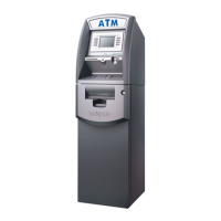
Details the physical dimensions and identifies key component locations of the ATM.
Identifies and describes the various components on the ATM's front panel.
Details the features and specifications of the ATM's cash dispensing unit (CDU).
Provides specifications and details about the ATM's receipt printer.
Lists the specifications and components of the ATM's main control board.
Specifies the required power, phone line, network, temperature, and humidity conditions.
Provides step-by-step instructions for installing the Hantle 1700w™ ATM.
Details the process for unpacking the ATM and verifying contents.
Guides through the physical steps of setting up the ATM, including anchoring.
Covers the hardware setup steps, including power, phone line, and key usage.
Details the initial setup procedures for the ATM's programming.
Explains how to access the Operator Menu using specific key sequences.
Provides steps for handling errors and accessing the Operator Function menu.
Describes the ATM's keypad layout and character mapping for operations.
Provides access to parameters for connecting the ATM to the processor.
Details accessing Secure Mode and the process for managing master keys.
Explains how to set the Terminal ID, which identifies the ATM on the network.
Describes the setting for how long the ATM waits to connect to the processor.
Explains setting the Routing ID, unique to each processor.
Guides on entering primary and secondary host telephone numbers for connection.
Explains the feature for sending system status signals to the processor.
Details how to enable remote monitoring using Hantle Remote Management Software.
Describes the feature for completing a Day Total operation automatically.
Allows configuration of system-wide settings like clock, languages, and volume.
Guides on setting the ATM's internal clock for local time.
Explains how to enable or disable on-screen languages like English, French, and Spanish.
Details how to adjust the ATM's speaker volume using a screw on the circuit board.
Discusses enabling/disabling ISO tracks for card reading, advising against changes.
Explains the ATM's three password levels and how to change them.
Provides access to adjust parameters for various ATM peripherals.
Allows setting the maximum column width for the receipt printer.
Covers modem speed and sound settings, advising against changes.
Explains setup for the EMV compliant card reader, requiring a reboot.
Details programming for the Cash Dispensing Unit (CDU) related to application and country.
Describes the automatic machine reboot feature and its scheduling.
Explains the unique serial number, its purpose, and format.
Controls surcharge information, BIN lists, receipt options, advertisements, and keypad lighting.
Details setting welcome and receipt header messages for customer interaction.
Explains how to set up BIN numbers to prevent surcharges on specific cards.
Covers optional functions like Select Receipt, Transfer to Credit, and Check Balance.
Guides on selecting the communication protocol to match the specific host processor.
Details setting surcharge rates, owners, and enabling/disabling the option.
Explains how to load and enable up to 8 graphic screens for advertisements.
Configures transaction parameters like dispense limits and denominations.
Sets the maximum amount of money a customer can withdraw per transaction.
Configures the type of bill each cassette dispenses and warns about key deletion.
Allows setting predefined cash withdrawal amounts for customer convenience.
Details network setup for TCP/IP communication, including IP address and port.
Provides instructions for opening and closing the ATM's security door.
Step-by-step guide to opening the ATM's security door and its locks.
Step-by-step guide to securely closing the ATM's security door.
Details how to open the top bezel of the ATM using the bezel key.
Provides instructions for closing the ATM's top bezel securely.
Explains how to operate and change the mechanical combination lock.
Guides on operating and changing the electronic lock, including default combinations.
Covers procedures for managing cash within the ATM.
Step-by-step guide for adding cash to the fixed cassette dispenser.
Instructions for emptying the reject bin in the fixed cassette dispenser.
Step-by-step guide for adding cash to removable cassette dispensers.
Instructions for emptying the reject bin in removable cassette dispensers.
Provides instructions on how to load new paper rolls into the receipt printer.
Controls bill counts and generates Day total and Cassette total reports.
Details the Day Total function for tracking ATM transaction activity and printing reports.
Explains the Cassette Total function for reporting bills loaded and dispensed.
Manages the ATM's electronic record of transactions, errors, and programming changes.
Details the process for printing the ATM's journal records in standard or condensed format.
Allows bypassing the journal marker to reprint previous records.
Resets the journal sequence number, useful after system changes.
Provides a way to visually inspect journal records on the screen.
Sets the journal marker to the most recent record without deleting data.
Provides access to statistical, troubleshooting, and error information reports.
Displays error descriptions and corrective actions for machine errors.
Shows current software revisions for troubleshooting and updates.
Generates a complete listing of all ATM programming details for troubleshooting.
Provides a running total of errors, listing them by occurrence count.
Presents running averages of transaction information, like withdrawals and deposits.
Introduces built-in diagnostic features to assist in troubleshooting ATM problems.
Tests the cash dispenser's ability to pull and send notes to the reject bin.
Performs a test to print a sample receipt, verifying printer functionality.
Tests the modem's dial-out capability by allowing a test phone number entry.
Tests the ATM's keypads by displaying a map and showing active keys.
Tests the card scanner's three tracks to ensure proper reading of magnetic stripes.
Describes the aging test used for factory quality control, running self-tests.
Explains the steps required to place the ATM into service for customer use.
Details the step-by-step process for a customer performing a cash withdrawal.
Outlines the steps for a customer to check their account balance at the ATM.
Explains the procedure for a customer to transfer funds between accounts.
Details the steps for properly closing down the ATM at the end of a period.
Guides on how to recover from errors, verify codes, and perform device initialization.
Describes the different formats and requirements for each master key mode.
Guides on entering master key components (Part A, Part B) and serial numbers.
Explains how to verify master key entry and check digits for accuracy.
Detailed steps for cleaning dispenser optical sensors using a cotton-swab.
Identifies the locations of optical sensors within the MCDU dispenser.
Identifies the location of an optical sensor at the lower rear portion of the dispenser.
Identifies sensor locations at the front of the TCDU (fixed cassette) dispenser.
| Display | LCD |
|---|---|
| Stacker Capacity | 200 notes |
| Counting Speed | 1, 500 notes/minute |
| Connectivity | USB |
| Power Supply | AC 100 ~ 240V, 50/60Hz |