Do you have a question about the Harbor Freight Tools Vulcan Migmax 215 and is the answer not in the manual?
Read all safety warnings and instructions. Failure to follow may result in serious injury.
Connect cables for flux-cored welding. Ensure proper polarity for gasless operation.
Connect cables for gas-shielded MIG welding. Set up gas cylinder and regulator.
Adjust feed tensioner to loosen it and move Idler Arm up. Tension for solid wire (3-5) and flux-cored (2-3).
Check and select correct feed roller for wire type and size. Ensure correct groove is used.
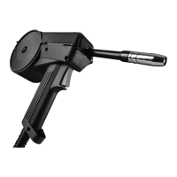
Connect Gun Cable Connector to Wire Feed mechanism. Ensure secure insertion.
Connect Wire Feed Control Cable. Ensure correct orientation and secure lock ring.
Hold wire securely. Cut off bent/crimped wire. Guide wire into liner.
Adjust feed tensioner to latch Idler Arm. Tension for solid wire (3-5) and flux-cored (2-3).
Remove Nozzle and unscrew Contact Tip counterclockwise.
Plug in 120VAC or 240VAC Power Cord into Power Input Socket.
Plug in and turn on Power Switch. Press Cold Wire Feed Switch to feed wire.
Check wire drive tension by feeding wire against wood. Adjust tension until wire bends.
Select compatible Contact Tip, install it. Replace Nozzle and cut wire to 1/2 inch stickout.
Wear full face shield, ear protection, gloves, respirator, and fire-resistant clothing.
Practice welds on scrap. Clean weld surfaces thoroughly with wire brush or grinder.
Learn to draw wire in steady line (stringer) or back and forth (weave) for welds.
Proper gun angles (push/drag) and Contact Tip to Work Distance (CTWD) for optimal welds.
Remove slag with chipping hammer. Clean weld with wire brush or angle grinder.
Test weld appearance by striking with hammer. Good weld deforms, poor weld breaks.
Understand how to increase or reduce workpiece heat and control weld penetration.
Solutions for excess, proper, and inadequate weld penetration based on causes.
Address gaps between welds or workpiece due to clamping, heat, or dirt.
Clean and inspect MIG Gun nozzle and contact tip before each use. Replace if damaged.
Solutions for wire not feeding properly: check pressure, roll size, cable, tension.
Fix wire bird's nest or stopping: adjust pressure, check tip size, cable connection, liner.
Schematic diagram showing the electrical connections within the welder.
| Brand | Harbor Freight Tools |
|---|---|
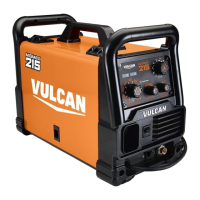
| Model | Vulcan Migmax 215 |
| Category | Welding System |
| Language | English |