Do you have a question about the Hardware House 20-7409 and is the answer not in the manual?
Covers shock prevention, code compliance, and avoiding specific electrical devices.
Ensures secure outlet box, joist support, and proper clearance for safe installation.
Includes avoiding moving parts, cleaning safely, and handling components correctly.
Ensure outlet box is marked for fan support, securely fastened, and supports 50 pounds.
Details mounting configurations, downrod use for sloped ceilings, and hanger support bars.
Inspect fan contents and disconnect power at the fuse box to prevent electric shock.
Verify outlet box suitability and secure fastening to structural members for stability.
Remove screws from canopy mating holes and loosen screws in slots for bracket removal.
Install the mounting bracket to the outlet box using provided screws and washers.
Prepare the downrod by removing the clamp pin and cross pin.
Place downrod assembly into canopy and yoke cover, feeding wires through.
Align downrod holes with coupling, insert cross pin and keeper pin, tighten set screws.
Attach blade holders to fan blades using screws and fabric washers.
Align motor screw holes with connection box U slot and attach blade assembly securely.
Lift fan onto mounting bracket, engaging notch on downrod ball with bracket ridge.
Connect house wiring to fan motor wiring using provided wiring nuts.
Slide wired remote receiver between mounting bracket and downrod ball.
Position canopy slots under bracket screws, lift, slide, rotate, and tighten securely.
Lift light pan to connection box screws, align holes, and tighten all screws.
Connect fan light terminals to motor terminals (black to black, white to white).
Install included bulbs, noting type A15C MAX 60W.
Attach glass shade to metal frame, secure to light pan, and tighten screws.
Ensure transmitter and receiver codes match for proper operation.
Details fan speed control (HI, MED, LOW, OFF) and light control (ON/OFF, DIMMER).
Mount the transmitter wall holder using two screws.
Explains fan direction (S/Forward, W/Reverse) for cooling and heating effects.
Check connections, brackets, and blade attachments twice yearly for security.
Clean with a soft, lint-free cloth; do not use water; no oiling required.
Check fuses, wiring, forward/reverse switch, or consult an electrician.
Verify screw tightness, avoid solid-state controls, and allow break-in period.
Ensure blade and bracket screws are tight; interchange blades if wobble persists.
Check wire connections, bulbs, or consult an electrician for light kit issues.
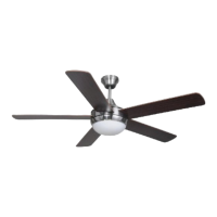
| Model | 20-7409 |
|---|---|
| Category | Fan |
| Blade Span | 52 inches |
| Number of Blades | 5 |
| Light Kit Included | Yes |
| Mounting | Ceiling |
| Blade Size | 52 inches |
| Motor Speed | 3 speeds |
| Power Source | Electric |
| Mounting Type | Ceiling |
| Material | Wood |