2
g) Disengage the Video PCB from its rear connector (CP601) by pushing back on the rear PCB; lift the
Video PCB up and out of the unit. It should still have an amber-colored 8 pin connector attached. Set the
PCB aside and out of the way.
h) Remove the (2) remaining screws (1 plated, 1 black) holding the DSP PCB to the chassis. The black
screw will loosen a small aluminum heatsink (for IC100); remove it.
i) Disengage the DSP PCB from its rear connector (CP401) by pushing back on the rear PCB; lift the DSP
PCB up and out of the unit; turn it upside down. It should still have an amber-colored 15 pin connector
attached.
j) Locate IC121 (see figure 3) and resolder if needed.
k) Replace parts in reverse order; remember to re-tighten the bottom bracket screws and replace the
heatsink. CAUTION: At the rear screws, if using a power tool, use care and minimum effort to avoid
damaging the various plastic receptacles.
l) Test the unit by following steps (a – i) in section 1.
FIGURE 3
MODEL
SERIAL NUMBER
120V
SERIAL NUMBER
230V
STATUS ACTION
AVR7000
TH0003-01000
to
TH0003-12085
TH0012-01000
to
TH0012-12386
IC121 may need re-
soldering
Check for sufficient solder
on pin 5 of IC121
AVR7000
TH0003-12086
and above
TH0012-12387
and above
NONE REQUIRED
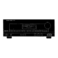
AVR7000 harman/kardon

 Loading...