2
USER GUIDE
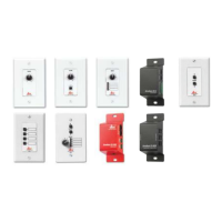
ZC Series Wall Controllers
RS-232
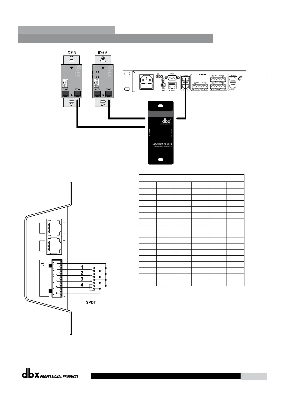
Diagram C
4
+V
3 2 1 INOUT
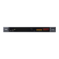
ZC-4
Diagram D
Switches SW1-SW4 correspond to switch inputs 1-4 on the ZC-4’s
EuroBlock connector. Each switch connected to the ZC-4 must
be a Single-Pole Double-Throw (SPDT). One pole of each switch
should be connected to the ground reference on the ZC-4’s
EuroBlock connector while the other pole should be connected
to the +V reference. Because there are four switch inputs, there
are 16 possible switch combinations. In the chart above, a “0”
corresponds to a switch connected to the ground reference; a “1” corresponds to the switch being connected to
the +V reference. None of the poles should be left hanging but should either be connected to +V or ground.
ZC-4 Binary Appnotes
SW4 SW3 SW2 SW1 Hex Setting
0 0 0 0 0 0
0 0 0 1 1 1
0 0 1 0 2 2
0 0 1 1 3 3
0 1 0 0 4 4
0 1 0 1 5 5
0 1 1 0 6 6
0 1 1 1 7 7
1 0 0 0 8 8
1 0 0 1 9 9
1 0 1 0 A 10
1 0 1 1 B 11
1 1 0 0 C 12
1 1 0 1 D 13
1 1 1 0 E 14
1 1 1 1 F 15
 Loading...