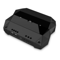
Do you have a question about the Harman JBL Club-5501 and is the answer not in the manual?
| Amplifier Class | D |
|---|---|
| Number of Channels | 1 |
| THD + N at Rated Power | < 1% |
| Signal-to-Noise Ratio | > 80 dB |
| Fuse Size | 30 A |
| Bass Boost | 0 - 12 dB |
Covers general instructions, warnings, and precautions for safe operation.
Includes specific safety advice for RF, radio receiver, laser, and battery products.
Provides techniques to reduce component damage from static electricity during handling.
Details the method for checking leakage current to ensure user safety.
Highlights key features like compact size, input types, crossovers, and advanced system compatibility.
Details power output, impedance, and signal-to-noise ratio for the mono amplifier.
Lists specifications for 4-channel and 5-channel amplifiers, including power and impedance.
Illustrates the amplifier's signal path and functional modules.
Shows the input selector, gain, low pass, bass, and phase control circuits.
Details the Class D amplifier stage, protection circuits, and output components.
Details the components and circuitry for the amplifier's power supply section.
Shows the IRS2092 Class D amplifier driver and output MOSFETs.
Illustrates the physical placement of components on the printed circuit board.
Details the routing of electrical traces and copper areas on the PCB.
Shows the assembly breakdown and lists parts with their positions and quantities.
Illustrates the steps and components involved in packaging the amplifier.
Lists items included in the packaging with their descriptions and quantities.
Lists all replaceable parts, their part numbers, descriptions, and quantities.