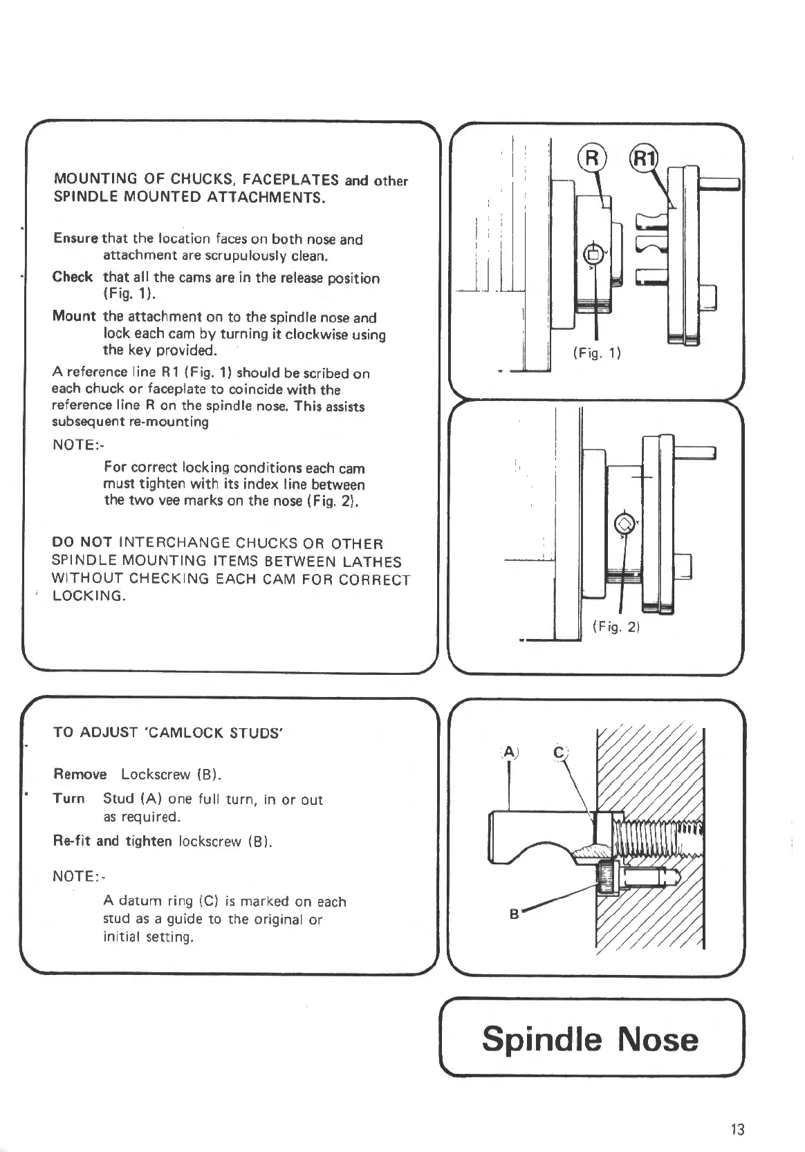
MOUNTING
OF
CHUCKS, FACEPLATE$ and other
SPINDLE
MOUNTED
ATTACHMENTS.
Ensure
that
the
location
faces
on
both
nose and
attachment are scrupulously clean.
Check
that
all
the
cams
are in the
release
position
(Fig.
1).
Mount the attachment
on
to
the spindle nose and
lock each
cam
by
turning
it
clockwise using
the key provided.
A reference I ine R 1 (Fig. 1) should
be
scribed
on
each chuck
or
faceplate
to
coincide
with
the
reference line R on the spindle
nose.
This
assists
subsequent re-mounting
NOTE:-
For correct locking conditions
each
cam
must tighten
with
its index line between
the
two
vee
marks on the nose (Fig. 2).
DO
NOT
INTERCHANGE
CHUCKS OR OTHER
SPINDLE
MOUNTING
ITEMS BETWEEN
LATHES
WITHOUT
CHECKING
EACH CAM FOR CORRECT
LOCKING.
TO
ADJUST
'CAMLOCK
STUDS'
Remove Lockscrew
lB).
Turn
Stud
(A)
one
full
turn,
in
or
out
as
required.
Re-fit
and
tighten
lockscrew ( B).
NOTE:
-
A
datum
ring (Cl is marked
on
each
stud
as
a guide
to
the original
or
initial setting.
I ;
I
.J
.J
.
(Fig. 1)
' '
(Fig. 2)
( Spindle Nose
)
13
 Loading...