\
2
The spindle bearing assembly is carefully set before despatch
of
the Lathe
from
our
Works
which
should ensure a high standard
of
performance
without
the
need
for
further
attention.
THE USER IS
ADVISED
NOT
TO
DISTURB
THIS
SETTING
DURING
NORMAL
USE
OF
THE
MACHI
NE
ANO
TO CONSULT OUR SERVICE
DEPARTMENT
IN
THE
UNLIKELY
EVENT OF
A
BEARING
PROBLEM.
WHERE ADJUSTMENT
IS
UNDERTAKEN
THEN
IT
IS
ESSENTIAL
THAT
THE
FOLLOWING
PROCEDURES
ARE
STRICTLY
COMPLIED WITH.
TO CHECK FOR CORRECT SETTING
Checks should
be
carried
out
with
the
headstock
in
a warm condition achieved
by
running
at
a
spindle
speed
of
800
rpm
for
approximately ten minutes.
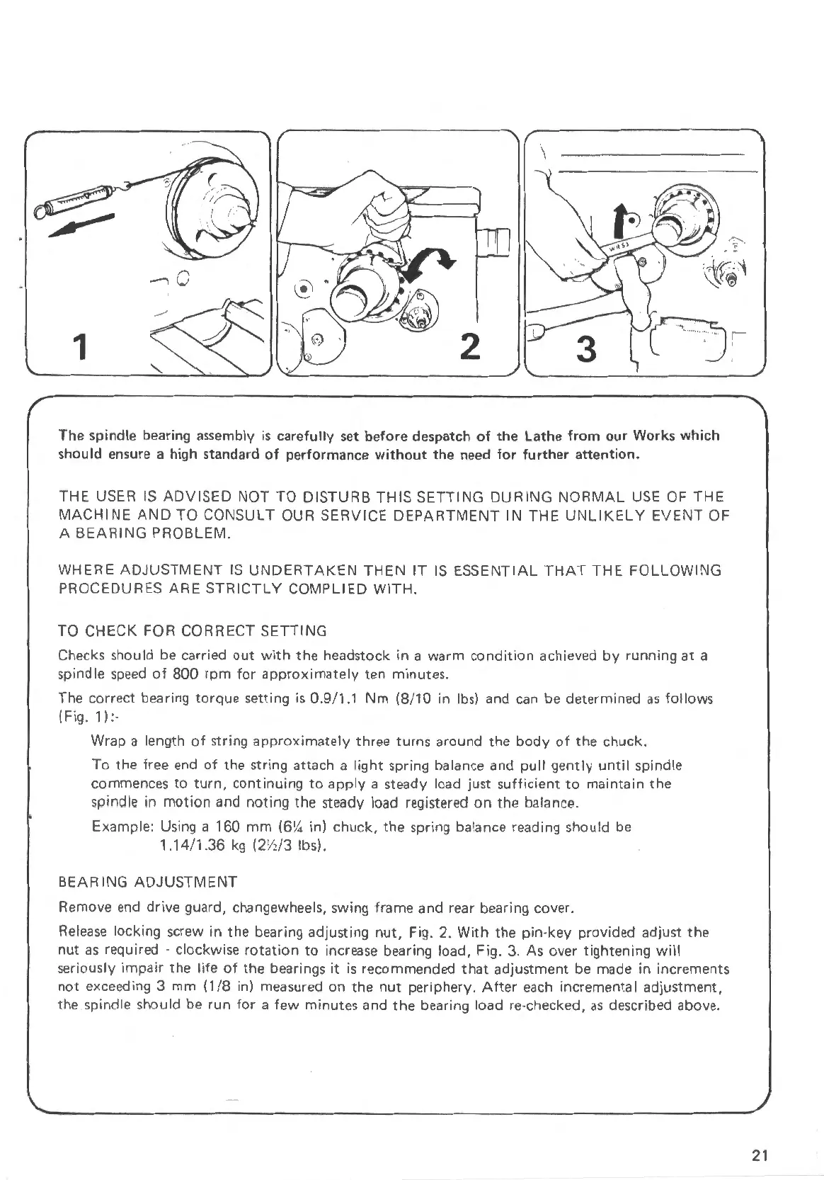
The correct bearing torque setting is 0.9/1.1
Nm
(8/10
in
lbs)
and
can
be determined
as
follows
( Fig.
1)
:-
Wrap a length
of
string approximately three turns around
the
body
of
the
chuck.
To
the free end
of
the string attach a light spring balance and
pull
gently
until
spindle
commences
to
turn,
continuing
to
apply a steady load just sufficient
to
maintain the
spindle
in
motion and noting the steady load registered
on
the balance.
Example: Using a 160
mm
(6¼ in) chuck,
the
spring balance reading should be
1.14
/1 .36
kg
(2½/3 lbs).
BEARING ADJUSTMENT
Remove
end
drive guard, changewheels, swing frame and rear bearing cover.
Release
locking screw
in
the bearing adjusting
nut,
Fig. 2.
With
the
pin
-key provided adjust the
nut
as
required · clockwise
rotation
to
increase bearing load, Fig. 3. As over tightening
will
seriously impair the
life
of
the bearings
it
is
recommended
that
adjustment
be
made
in
increments
not exceeding 3 mm
(1/8
in) measured on
the
nut
periphery.
After
each
incremental adjustment,
the spindle should
be
run
for a few minutes and the bearing load re-checked,
as
described above.
21
 Loading...